


232
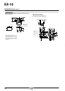
EX-10
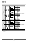
I/O CIRCUIT AND WIRING DIAGRAMS
EX-11Ⅺ EX-13Ⅺ
EX-19Ⅺ EX-14Ⅺ
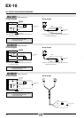
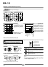
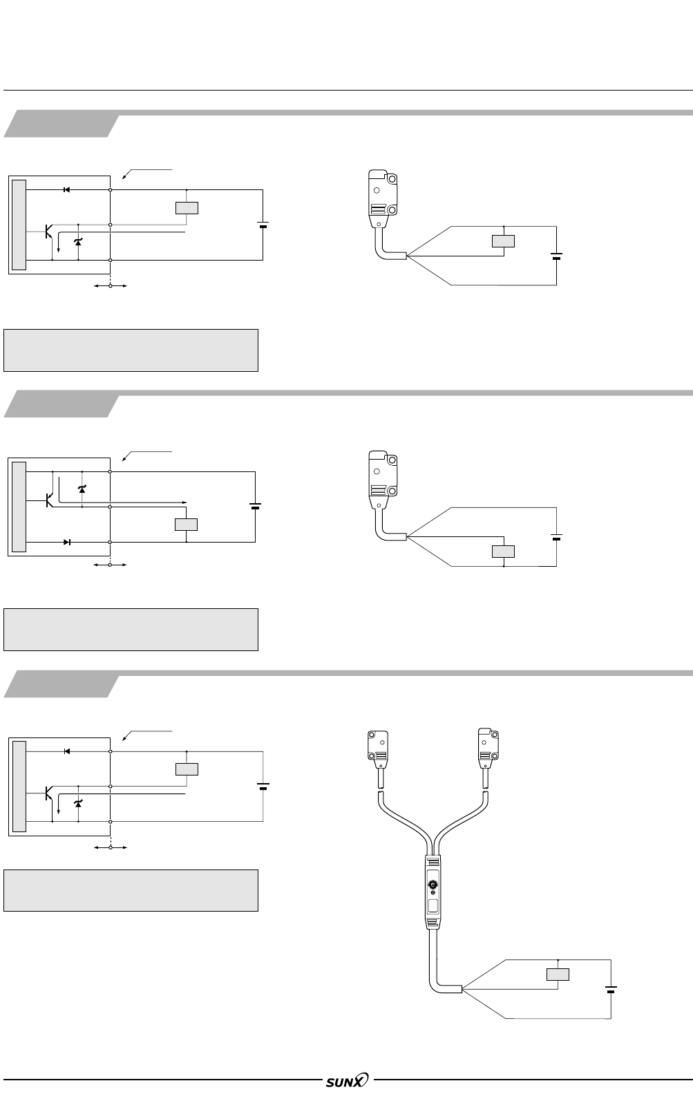
I/O circuit diagram
NPN output type
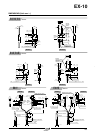
PNP output type
NPN output type
Wiring diagram
Users’ circuitInternal circuit
Color code
50 mA max.
Sensor circuit
Tr
D
ZD
Load
(Brown)
םV
(Black)
Output (Note)
(Blue) 0 V
ם
מ
12 to 24 V DC
ע10 %
Note:The emitter of the thru-beam type sensor does not
incorporate the output.
Note:The emitter of the thru-beam type sensor does not
incorporate the black wire.
Symbols … D : Reverse supply polarity protection diode
Z
D: Surge absorption zener diode
Tr : NPN output transistor
ם
מ
Brown
Black (Note)
Blue
Load
12 to 24 V DC
ע10 %
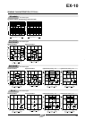
EX-11Ⅺ-PN EX-13Ⅺ-PN
EX-19Ⅺ-PN EX-14Ⅺ-PN
Users’ circuitInternal circuit
D
50 mA max.
ZD
Tr
Load
(Black) Output (Note)
(Blue) 0 V
12 to 24 V DC
ע10 %
ם
מ
Sensor circuit
Color code
(Brown)
םV
Symbols … D : Reverse supply polarity protection diode
Z
D: Surge absorption zener diode
Tr : PNP output transistor
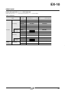
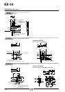
EX-15 EX-15E
EX-17 EX-17E
I/O circuit diagram Wiring diagram
Users’ circuitInternal circuit
Color code
100 mA max.
Sensor circuit
Tr
D
ZD
Load
(Brown)
םV
(Black) Output
(Blue) 0 V
ם
מ
12 to 24 V DC
ע10 %
Symbols … D : Reverse supply polarity protection diode
Z
D: Surge absorption zener diode
Tr : NPN output transistor
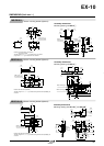
ם
מ
12 to 24 V DC
ע10 %
Load
Brown
Black
Blue
ם
מ
Brown
Black (Note)
Blue
Load
12 to 24 V DC
ע10 %
Note:The emitter of the thru-beam type sensor does not
incorporate the output.
Note:The emitter of the thru-beam type sensor does not
incorporate the black wire.
I/O circuit diagram Wiring diagram
08/2005