


1001
29
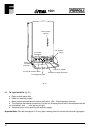
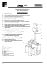
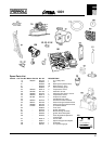
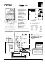
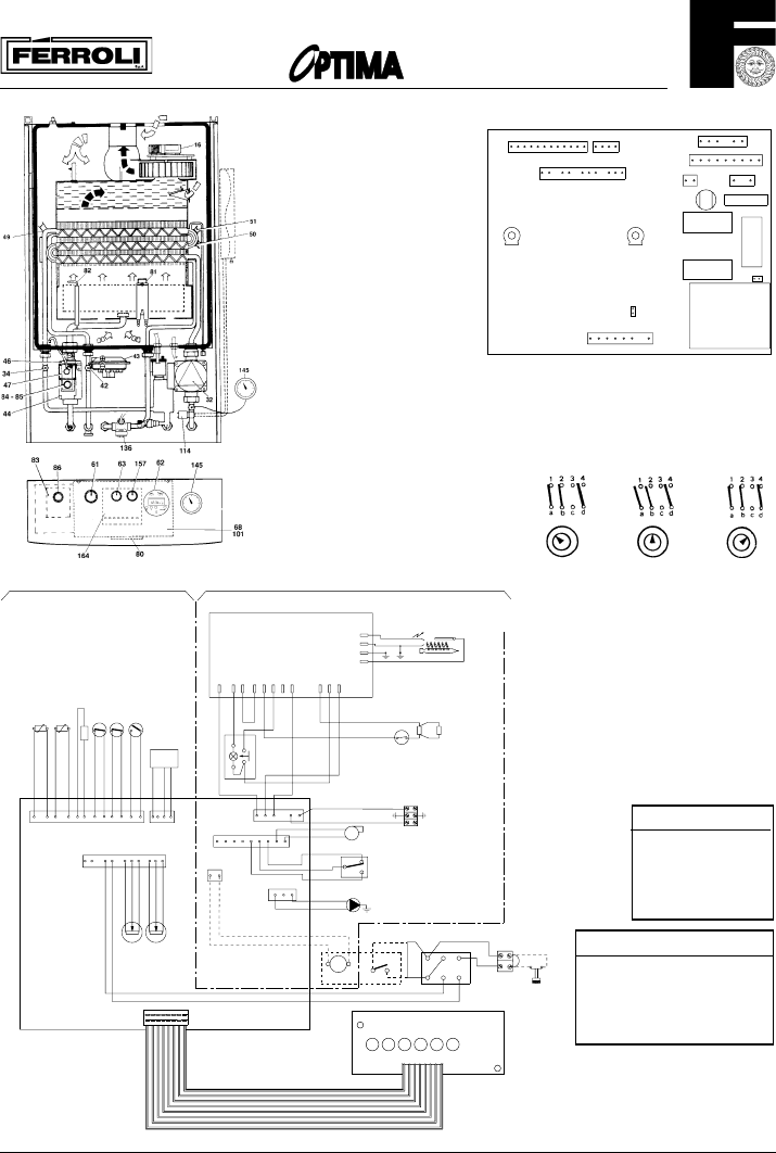
16 Fan
32 Central heating pump
34 C.H. flow temperature sensor
42 D.H.W. temperatuure sensor
43 Air pressure switch
46 Operator gas valve
47 Modulating regulator
(MODUREG) gas valve
49 Overheat cut-off thermostat
50 Heat exchan. limit thermostat
51 Heat exchan. frost thermostat
61 C.H. selector switch
62 Time clock
63 C.H. boiler thermostat
68 Control box with P.C.B.
72 Room thermostat (not fitted)
80 Five pole terminal 240V + 24V
81 spark electrode
82 Flame sensing electrode
83 Automatic ignition control panel
84 1. gas valve operator
85 2. gas valve operator
86 automatic control reset knob
101 P.C.B.
114 Low water pressure switch
136 Flowmeter
145 C.H. Pressure switch
157 D.H.W. thermostat
164 Fault diagnostic/temperature control panel
12 1
TR1
X4
X6
234
X2
RY1
X1
2AT
230V
50Hz
1
1110
7263512 910
12
P1
X3
6 5
3
4
1
F1
987654321
X8
123456789
X5
1
2
X7
JP4
13
L7
RY2
RY4
JP1
P2
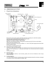
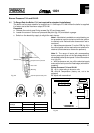
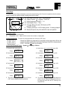
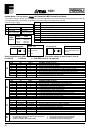
P1 = C.H. max. output (to be set on site)
P2 = D.H.W. temperature (factory set)
JP1 and JP4: Jumpers
JP1 Is not required
JP4 Is not required
61. C.H. selector switch
Heating timed
and hot water
Hot water only Heating
continuous and
hot water
NOTE:
THE TRANSFORMER ON THE P.C.B. HAS A
BUILT-IN OVERHEAT PROTECTION.
IF THIS IS OPEN, ALL LED'S WILL BE OFF BUT
THE C.H. PUMP (32) WILL RUN
SWITCH OFF THE BOILER FOR AT LEAST
20 MINUTES
SHORT CIRCUIT 12-13
- BOILER STARTS FOR C.H.
- WAITING TIME IS EXCLUDED
- MAX BURNER PRESSURE C.H.
CAN BE CHEDKED/SET WITH P1
A D.H.W. FLOW-
SWITCH (ON-OFF) CAN
BE CONNECTED TO
TERMINALS 1 AND 3
CONNECTOR X2
CONNECTOR X3
X6
12 1476521313
81
8
X3
X4
X5
9
82
1
129
3
83
4
2
49
84
85
43
47
32
12 8
16
+
42
VMF7
X5
54 213
80
L
N
230V
24 V
11
230V ~ 50 Hz.
X1
10
OUT
9
136
43
34
876
1
1
2
312
5
21
4
13 7 26
1
35910
12
6
X2
X4
X7
X3
X6
197 26
51
-
5284
3
1
80
5
b
a
d
2
4
4
5
M
24V
72
12
3
50114
X8
LD2
63 157
8
1
L6L5L4L3L2L1
X1