


1001
10
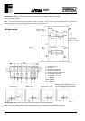
Flue system
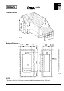
The boiler allows the flue outlet to be taken from the rear of the boiler or from either side.
A standard flue length of 0.75 metres is provided. Alternative lengths of two or three metres can be supplied (equivalent
to wall thicknesses of up to 565, 1815 and 2815 mm for rear flues and deduct 91 mm plus distance from side wall for
side outlet flues).
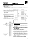
It is absolutely essential, to ensure that products of combustion discharging from the terminal cannot re-enter the
building, or enter any adjacent building, through ventilators, windows, doors, natural air infiltration, or forced ventilation/
air conditioning.
Gas Supply
If necessary the local Gas Region should be consulted, at the installation planning stage, in order to establish the
availability of an adequate supply of gas.
An existing service pipe must not be used without prior consultation with the Local Gas Region.
A gas meter can only be connected by the Local Gas Region, or by a Local Gas Region's Contractor.
Installation pipes should be fitted in accordance with BS6891-1988.
Appliance inlet working pressure must be 20 mbar MINIMUM.
Pipework from the meter to the combination boiler must be of an adequate size.
The boiler requires 3.3 m
3
/h (116 ft
3
/h) of natural gas.
Do not use pipes of a smaller size than the combination boiler inlet gas connection.
The complete installation must be tested for gas soundness and purged as described in BS6981-1988. All pipework
must be adequately supported. An isolating gas valve is provided and should be fitted on the manifold assembly.
Water System
Central Heating
It must be a sealed system. Detailed recommendations are given in BS6798, BS5449, BS6700 and CP342 Part. 2.
Pipework not forming part of the useful heating surface should be insulated to prevent any heat losses or possible freezing
(i.e. in roof spaces or ventilated underfloor spaces). Drain taps should be positioned at the lowest point of the system
in accessible locations to permit the whole system to be drained down. The drain taps should be in accordance with
BS2879. Copper tubing to BS2871, Part. 1 is recommended for water carrying pipework. Pipework in horizontal runs
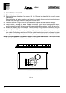
should have a gradient where possible to facilitate the removal of air. It should be ensured that the boiler heat exchanger
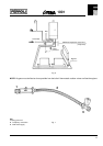
is not a natural point for collecting air. A typical heating system with domestic hot water circuit is illustrated in fig. 6.
Important - A bypass must be fitted to ensure a minimum flow rate through the boiler of 6 l/min. The bypass should
be fitted as far as possible from the boiler if thermostatic radiator valves are fitted throughout.
Make up Water
Provision must be made for replacing water lost from sealed system. Reference should be made to BS6798, for
methods of filling and making up sealed systems. There must be no direct connection between the boiler's central
heating system and the mains water supply. The use of mains water to charge and pressurise the system directly,
is conditional upon the Local Water Byelaw. Again any such connection must be disconnected after use.
Domestic Hot Water
Always fit a water softener or descaler in «hard water areas». A 15 mm copper connection point on the boiler jig
bracket for attaching to the main supply is provided. The maximum domestic water pressure for the inlet supply is 10
bar (145 P.S.I.). If the cold mains supply exceeds 5 bar (72 P.S.I.), a water governor or pressure reducing valve must
be fitted by the installer into the mains supply in an inconspicuous but accessible position preferable between 3 and 5
metres (10-16 ft) before the appliance.
Such a valve must be approved by the Water Research Council.
Attention - Is drawn to the Model Water Byelaws.
Fittings manufactured from duplex (alpha-beta) brass are not acceptable for underground use and certain water
undertakings will not accept their use above ground.