


1001
13
Installation
Note - To mount the boiler on the wall, a two person lift will be needed.
1.0 UNPACKING
The appliance is delivered in 2 cartons.
1.1 The large carton contains the boiler, and the Installation/Servicing and Users Instructions.
1.2 The second carton contains the mounting jig assembly, complete with isolating valves, the assembly
fixing screws and wall plugs (x4), the boiler mounting nuts and washers (x2), drilling template, flue
assembly and flue bend.
When the cartons are unpacked examine for any signs of damage in transit. All protective plastic should be
left in place until installation is complete.
2.0 FIXING THE MOUNTING JIG ON THE WALL (Rear Wall Flue Applications)
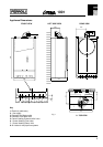
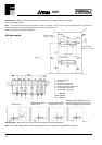
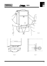
2.1 Select the boiler location carefully ensure that all requirements given in previous text are satisfied.
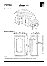
Fig. 10 will also give guidance to fixing dimensions.
2.2 Locate template on wall, mark the positions of the four jig bracket fixing holes and the flue opening.
2.3 Carefully cut the circular hole (118 mm minimum diameter) for the flue assembly.
2.4 Using a 10 mm drill, drill 70 mm deep holes to accept the wall plugs, and insert wall plugs.
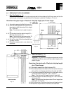
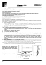
2.5 Fit the mounting jig assembly using the four fixing screws provided (Ensure that all the service cocks
are in the OFF position). Operate valves several times to ensure they are free.
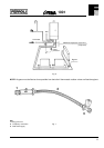
2.6 With the exception of the connection to the pressure relief valve, make all the water and gas
connections to the jig bracket valves. Fully tighten (fig. 11). Water connections can be made with
compression or capillary fittings (before the gas inlet to the boiler there must be at least 100 mm of
straight before any bends).
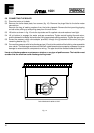
3.0 FIXING THE MOUNTING JIG ON THE WALL (Side Wall Flue Applications)
3.1 Select the boiler location carefully ensuring that all the requirements given in previous text are satisfied.
Fig. 10 will aso give guidance.
3.2 Locate the template on wall and mark the position of the four jig bracket fixing holes.
3.3 Using a 10 mm drill, drill 70 mm deep holes to accept the wall plugs, and insert wall plugs.
3.4 Fit the mounting jig assembly using the four fixing screws provided.
3.5 Extend a horizontal line from the centre of the rear flue outlet to the side wall.
3.6 Mark the centre line (vertically) for the flue assembly hole, and mark the centre of the hole.
3.7 Carefully cut the circular hole (118 mm minimum diameter) for the flue assembly.