


1001
15
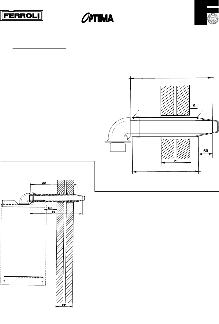
4.0 PREPARING THE FLUE ASSEMBLY
4.1
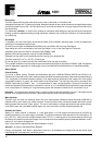
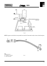
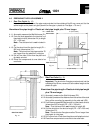
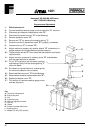
Rear Flue Outlet (fig. 12)
Important - The aluminium flue pipe must protrude into the outside grill by 60 mm, never cut it to the
same length as the plastic air pipe (aluminium flue pipe = plastic air inlet pipe + 70 mm !).
Aluminium flue pipe length = Plastic air inlet pipe length plus 70 mm longer.
4.1.1 Accurately measure the Wall thickness (P1)
4.1.2 From the end opposite to the terminal, cut
the plastic air duct (dimension A1) to length
(P1 + 192 mm).
Note - That the terminal is not included in
A1.
4.1.3 Cut the aluminium flue duct to length (P1 +
262 mm) (dimensions F1).
Note - The aluminium flue pipe must be 70
mm longer than the plastic air inlet pipe.
4.1.4 Drill a 3 mm hole 15 mm from the plain end
of plastic air duct.
4.1.5 Place flue components to one side to be
used later.
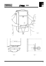
Side Flue Outlet
Fig. 13
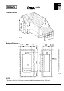
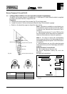
4.2 Side Flue Outlet (fig. 13).
Important - The aluminium flue pipe must protrude into the
outside grill by 60 mm, never cut it to the same length as the
plastic air pipe.
Aluminium flue pipe length = Plastic air inlet pipe length
plus 70 mm longer.
4.2.1 Accurately measure the Wall thickness (P2).
4.2.2 Accurately measure the distance from the centre of the stud
fixing of the mounting jig assembly to the side wall (Q2).
4.2.3 From the end opposite to the terminal, cut the plastic air duct
(dimension A2) to length (P2 + Q2 + 180 mm).
Note - That the terminal is not included in length A2.
4.2.4 Cut the aluminium flue duct to length (P2 + Q2 + 250 mm)
(dimension F2).
Note - The aluminium flue pipe must be 70 mm longer than
the plastic air inlet pipe.
4.2.5 Drill a 3 mm hole 15 mm from the plain end of plastic air duct.
4.2.6 Place flue components to one side to be used later.
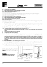
Rear flue Outlet
Fig. 12
Fixing
screw
F1 (Flue outlet)
A1 (Air intake)
K = 10 mm min.
60 mm max.
Fixing
screw