


F3S-B
3
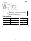
Ordering Information — continued
Description Part number
Protective height Weight (without
accessories)
Optical
resolution
Beam
pitch
No. of
beams
Stand-Alone Master Unit Slave Unit
300 mm 0.9 kg
80 75 mm
4 F3S-B047P F3S-BM047Pjj F3S-BS047
450 mm 1.2 kg
8
0
5
6 F3S-B067P F3S-BM067Pjj F3S-BS067
600 mm 1.5 kg 8 F3S-B087P F3S-BM087Pjj F3S-BS087
750 mm 1.8 kg 10 F3S-B107P F3S-BM107Pjj F3S-BS107
900 mm 2.1 kg 12 F3S-B127P F3S-BM127Pjj —
1,050 mm 2.5 kg 14 F3S-B147P F3S-BM147Pjj —
1,200 mm 2.8 kg 16 F3S-B167P F3S-BM167Pjj —
1,350 mm 3.1 kg 18 F3S-B187P F3S-BM187Pjj —
1,500 mm 3.4 kg 20 F3S-B207P F3S-BM207Pjj —
1,650 mm 3.7 kg 22 F3S-B227P F3S-- BM227Pjj —
Note: jj indicates No. of beams o f the connected Sl ave Unit. For 75 mm beam-pitch type: 04, 06, 08 or 10.
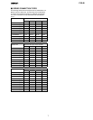
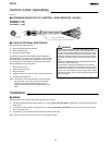
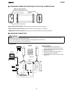
J EXTENSION CABLE (SET OF 2) ORDER SEPARATELY
Description Part number
3 meters F39-JB1A
7 meters F39-JB2A
10 meters F39-JB3A
J ACCESSORIES
Description Part number
Optional Function Kit F39-EU1E
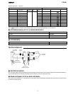
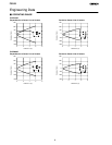
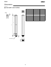
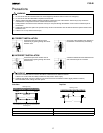
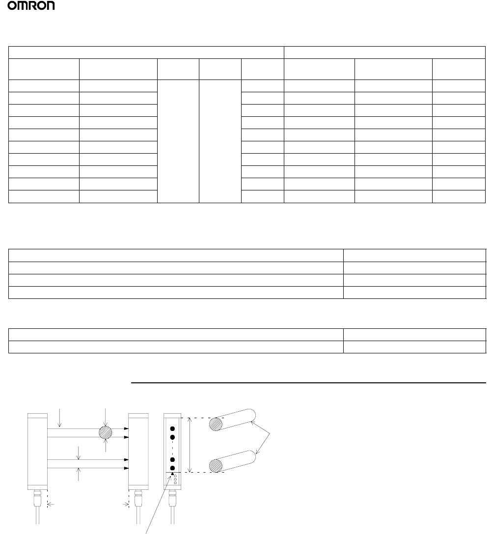
Nomenclature
1
2
n
Receiver
Emitter
Beam pitch
(Optical axispitch)
Beam linemark
(Optical--axis line mark)
Detection distance
n-- 1
No. of beams
(Optical axes)
Optical
resolution
Protective
height
Limit position
for detection
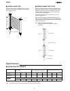
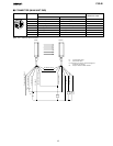
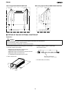
J PROTECTIVE HEIGHT
The F3S-B can detect in the area indicated by protective height in the figure below. The protective height is from the Beam-Line Mark (or
may be called Optical- Axis-Line Mark) above the indicator area to the end of the yell ow metal case.
J BEAM- LINE MARK (OPTICAL-AXIS LINE MARK)
The Center Line for the Beam (i .e., the Center Line for the Optical Axis) is i ndicated by the triangle mark. This position is a reference line
for measuring safety distance.