


F3S-B
12
O
pt
i
ons
(
O
r
d
er
S
eparate
l
y
)
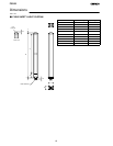
Unit: mm
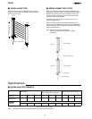
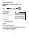
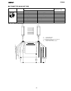
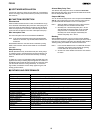
J EXTENSION CABLE (SET OF 2: EMITTER = GRAY, RECEIVER = BLACK)
F39-JB1A (L = 3 m)
F39-JB2A (L = 7 m)
F39-JB3A (L = 10m)
42 L
M12
∅ 15
Round vinyl --insulated c ord
5.7 mm dia. (32 @ 0.1 mm dia. each) 8 cores
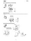
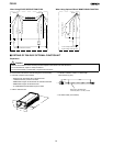
J F39-EU1E OPTIONAL FUNCTION KIT
This set includes the following items:
D F39-U1E Optional Function Software
D F39-E1 Interface Unit
D F39-JB1C Interface Cable
The F39-U1E Optional Function Software is the WINDOWSR
based software for use with the F39-E1 Interface Unit to program
the F3S-B Safety Light Curtain. The software i s provided on one
3.5 inch floppy disk. The software has the features listed below.
Set the followi ng functions to the F 3S-B:
1. Start interlock function
2. Relay monitoring function
3. Blanking function
D Display each axis and each input line condition of the F3S-B
D Change the ON del ay time
Note: The F3S-B is not in normal operation during connection
with the F39-E1. The control outputs are held in their
OFF-state. For detailed information please refer to
Details of Optional Function Kit, E39-EU1E in this data
sheet.
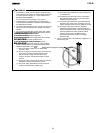
WARNING
After setting the blanking function, check that the F3S-B
detects a test rod at any position in the F3S-B detection zone
through which a person reaches the hazardous part of the
machine. If any posi tions are found by check above, install
protective structures to there to prevent intrusion which the
F3S-B can not detect. Failure to do so may result i n serious
injury.
Perform the installation check and the periodical inspection
described in the F3S-B manual.
Disconnect the outputs of the F3S-B from the load w hen
programming it using the F39-U1E software and with F39-E1
Interface Unit. Failure to do so may result in serious injury.
Do not connect the F39-E1 to a power supply wi th a voltage
higher than 24 VDC +20 %. Do not connect the F39-E1 to an
AC pow er supply.
!
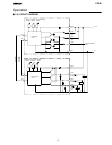
Installation
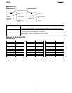
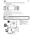
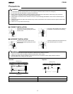
J WIRING
Disconnect all sources of power before wiring the F3S-B to a machine.
D Connect the emitter extension cable (F39-JBjA-- L optional, gray color outer jacket) to the emitter. (The emitter uses gray color
plastic caps.)
D Connect the receiver extension cabl e (F39-JBjA--D optional, black color outer jacket) to the receiver. (The receiver unit uses
black color plastic caps.)
D Connect the 0 V line of the power supply directly to protective earth (PE).
Note: Be sure to wire correctly. Failure to do so may damage the F3S-B.