


F3S-B
13
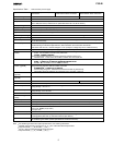
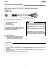
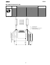
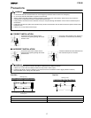
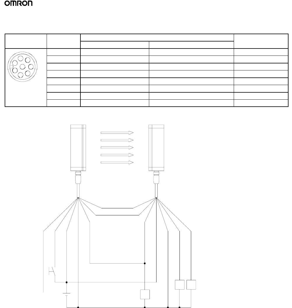
J CONNECTOR (MAIN UNIT END)
Front view Pin no. Signal name Wire color
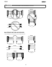
Receiver Emitter
of Extension Cable
1 Control output 2 Relay monitoring input White
1
7
6
2 24 VDC 24 VDC Brown
1
2
8
6
5
3 Control output 1 External test input Green
2
8
5
3
4
4 Instability output Interlock selection input Yellow
3
4
5 RS-485 (A) RS-485 (A) Grey
6 RS-485 (B) RS-485 (B) Pink
7 0V 0V Blue
8 N.C. / reserved N.C. / reserved Red
Note: N.C. / reserved: do not connect
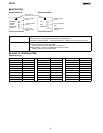
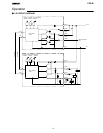
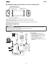
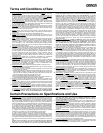
RS-- 485(A) (Grey 5)
RS-- 485(B) (Pink 6)
Receiver
Emitter
K2
K1
K3
E1
S1
E1: 24 VDC Power supply
S1: External testswitch
K1, K2: Relay o r PLCinput to control the dangerous
movement ofa machine
K3: Relayto indicate unstable condition
24 VDC(Brown 2)
Ext. test (Green 3)
Relay monitoring (White 1)
0V(Blue7)
Output 1 (Green 3)
Instability (Yellow 4)
Interlock selection (Yellow4)
24 VDC(Brown 2)
0V(Blue7)
Output2(White1)