


F3S-B
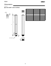
15
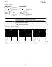
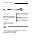
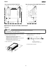
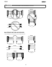
J COMPONENT NAMES AND FUNCTIONS OF THE F39-E1 INTERFACE UNIT
SEND to HS-485 indicator (Red)
SEND to HS-232C indicator (Yellow)
M8 Connector (RS-485)
9pin D-Sub Connector
(HS-232C)
Communication indicator (Green)
SEND to RS-485 Indicator (Red) Lit when the F39-E1 sends data to the F3S-B via RS-485.
SEND to RS -232C Indicator (Yellow) Lit w hen the F39-E1 sends data to the PC via RS-232C.
COMMUNICATION Indicator (Green) Flashing during communication between the F3S-B and the F39-E1.
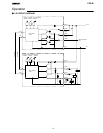
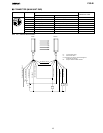
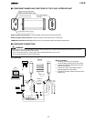
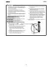
J HARDWARE CONNECTION
WARNING
Disconnect the outputs of the F3S-B from the load w hen programming it usi ng the F39-U1E software and with F39-E1 Interface
Unit. Fail ure to do so may result in serious injury.
Do not connect the F39-E1 to a pow er supply with a voltage higher than 24 VDC +20 %.
Do not connect the F39-E1 to an AC power supply.
!
Wiring Diagram
PC
See
Note.
-JB1C
Receiver
0V(Blue3)
+24V(Brown 1)
F39-- E 1
F39
F3S- B
No.1 axis
RS-232C
Open Output 1 (Green 3)
Open Output 2 (White 1)
RS-485 (B)
(Pink 6 )
RS-485 (B) (White 2)
0V (Blue 7)
0V (Blue 7)
RS-485 (A)
(Grey 5 )
24 VD C (Brown 2 )
24 VD C (Brown 2 )
Wiring Procedure
1. For wiring connections, use the F3S-B
Instruction Manual (enclosed with the product).
2. Connect the Interface Cable (F39-JB1C) to the
Interface Unit (F39-E1).
3. Connect the 4 wires of the Interface Cable to
each appropriate line of the F3S-B.
4. Connect an RS-232C Cable to the PC and to the
Interface Unit.
RS-485 (A) (Black 4 )
See
Note.
Emitter
F39-- U 1E