


Page 37 of 40
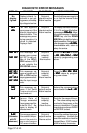
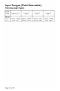
DISPLAY
No
display
lighted
FAILFAIL
FAILFAIL
FAIL
tESttESt
tESttESt
tESt
CHEC SP1CHEC SP1
CHEC SP1CHEC SP1
CHEC SP1
CHEC SP2CHEC SP2
CHEC SP2CHEC SP2
CHEC SP2
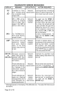
CHEC SPL1CHEC SPL1
CHEC SPL1CHEC SPL1
CHEC SPL1
CHEC SPH1CHEC SPH1
CHEC SPH1CHEC SPH1
CHEC SPH1
or
CHEC SPL2CHEC SPL2
CHEC SPL2CHEC SPL2
CHEC SPL2
CHEC SPH2CHEC SPH2
CHEC SPH2CHEC SPH2
CHEC SPH2
CHECCHEC
CHECCHEC
CHEC
LorELorE
LorELorE
LorE
SEnCSEnC
SEnCSEnC
SEnC
ArEAArEA
ArEAArEA
ArEA
(Alternates
with PV
when near)
MEANING
Display is blank. In-
strument is not get-
ting power, or the sup-
ply voltage is too low.
Fail test appears
upon power up if the
internal diagnostics
detect a failure. This
message may occur
during operation if a
failure is detected.
Displays flash.
This message will
appear upon power
up if SP1 is set out-
side of the SPL1/
SPH1 values or SP2
is set outside the
SPL2/SPH2 values.
This message ap-
pears at power up if
SPL or SPH values
are programmed out-
side the input range
ends.
This message ap-
pears if the Serial
Communications
has timed out.
Sensor Rate of
Change exceeded
the programmed lim-
its set for SEnC. Ap-
pears in display of
affected zone.
This message appears
if the ambiient temper-
ature of the control is
near or out of range or
RJC sensor is broken.
SP OUTPUTS
Set point
outputs inactive
Alarm inactive
Set point
outputs inactive
Alarm inactive
Set point
output(s)
inactive
Alarm active
Set point
output(s)
inactive
Alarm inactive
Set point
outputs active
Alarm inactive
Set point
output(s)
inactive.
Alarm Active
Set point
outputs active
Alarms active
ACTION REQUIRED
Check that the power supply is
on, or that the external fuses
are good.
The display alternates between
FAILtESt and one of the follow-
ing messages:
FACtFACt
FACtFACt
FACt
dFLtdFLt
dFLtdFLt
dFLt: Mem-
ory may be corrupted. Press the
ENTER key and the DOWN
ARROW key to start the factory
default procedure. Recheck con-
troller programming.
rEtrEt
rEtrEt
rEt
FACtFACt
FACtFACt
FACt:
Unrecoverable error, return to
factory for service.
Correct the
SP1SP1
SP1SP1
SP1,
SP2SP2
SP2SP2
SP2.or adjust
the
SPL1SPL1
SPL1SPL1
SPL1,
SPL2SPL2
SPL2SPL2
SPL2,
SPL2SPL2
SPL2SPL2
SPL2, or
SPH2SPH2
SPH2SPH2
SPH2
values by programming new
values.
Correct the
SPL1SPL1
SPL1SPL1
SPL1,
SPH1SPH1
SPH1SPH1
SPH1,
SPL2SPL2
SPL2SPL2
SPL2,
or
SPH2SPH2
SPH2SPH2
SPH2 values by program-
ming new values.
Restore the communications
line and switch the
LorELorE
LorELorE
LorE to
LOCLOC
LOCLOC
LOC.
Check for the cause of the er-
ror. The value setting may be
too slow for the process, or the
sensor is intermittent. Correct
the problem and press INDEX
and ENTER to reset.
Correct the ambient tempera-
ture conditions. Ventilate the
area of the cabinet or check for
clogged filters. If RJC broken,
return to factory for service.
DIAGNOSTIC ERROR MESSAGES