


Page 12 of 40
OPERATION OF SELF TUNE® FUNCTION
Self Tune® allows automatic selection of the necessary parameters to
achieve best control operation from your C N 74000 Series control. If you are
using the control output as a simple on-off function (e.g.
Out1Out1
Out1Out1
Out1 set for
OnOFOnOF
OnOFOnOF
OnOF),
none of the following will apply.
Theory of Operation
The Self Tune function calculates the
Pb1Pb1
Pb1Pb1
Pb1,
rES1rES1
rES1rES1
rES1, and
rtE1rtE1
rtE1rtE1
rtE1 parameters under
the
PID1 tunEPID1 tunE
PID1 tunEPID1 tunE
PID1 tunE selection,
Pb2Pb2
Pb2Pb2
Pb2,
rES2rES2
rES2rES2
rES2, and
rtE2rtE2
rtE2rtE2
rtE2 parameters under the
PID2 tunEPID2 tunE
PID2 tunEPID2 tunE
PID2 tunE
selection, the
Fbd1Fbd1
Fbd1Fbd1
Fbd1 and
Frt1Frt1
Frt1Frt1
Frt1 parameters, and the
Fbd2Fbd2
Fbd2Fbd2
Fbd2 and
Frt2Frt2
Frt2Frt2
Frt2 parameters,
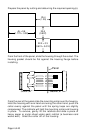
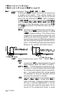
as shown in the Secondary Menu . These values are determined by measuring
the response of the process connected to the control. When Self Tune is
started, the control temporarily acts as an on-off control. While in this mode
the control measures the overshoot and undershoot of the process, and the
period of the process (the time from peak value to the next peak value). These
measurements are collected over a period that lasts three periods of overshoot
and undershoot. The data collected over this time is then compared and
calculated into final PID and Fuzzy Logic values. The effect of Fuzzy Logic
on the process is still controlled by the
Fi 1Fi 1
Fi 1Fi 1
Fi 1 and Fi 2 (fuzzy intensity) settings.
If
Fi 1Fi 1
Fi 1Fi 1
Fi 1 or Fi 2 is
00
00
0, the
Fbd1Fbd1
Fbd1Fbd1
Fbd1,
Frt1Frt1
Frt1Frt1
Frt1,
Fbd2Fbd2
Fbd2Fbd2
Fbd2, and
Frt2Frt2
Frt2Frt2
Frt2 will be calculated, but will
have no effect.
The calculations for Zone 1 and Zone 2 are completely independent. Each zone
has separate Self Tune and Fuzzy Logic parameters.
Set Point 2 Tracking
Some applications will call for Set Point 2 to follow or 'track' the setting for
Set Point 1. This can be done by changing the S2t setting in the Secure Menu
(edit set for 2 or 3). For a tracking SP2, set S2t to dE.
The Factory Default setting for S2t is ABS, making SP2 completely
independent of SP1.
When setting
SP2SP2
SP2SP2
SP2 value when Set Point 2 is programmed as deviation (
S2tS2t
S2tS2t
S2t
=
dEdE
dEdE
dE), set the difference in value from the Set Point 1 (
SP1SP1
SP1SP1
SP1) desired. For
example if Set Point 2 is required to be 5 degrees below the
SP1SP1
SP1SP1
SP1, then set
SP2SP2
SP2SP2
SP2 to
-5-5
-5-5
-5. If Set Point 2 is required 20 degrees above the
SP1SP1
SP1SP1
SP1, then set
SP2SP2
SP2SP2
SP2
to
2020
2020
20. If
SP1SP1
SP1SP1
SP1 is changed, the
SP2SP2
SP2SP2
SP2 setting will continue to hold the same
relationship as originally set.
When setting SP2 value when Set Point 2 is programmed as absolute (S2t
= AbS), simply set the value at which the alarm is to occur.