


25
TRANSFORMER
240V
24V
CONTACTOR
LIMITS
TOP
ELEMENTS, 10.0/10.8 KW
ELEMENTS
BOTTOM ELEMENT, 5.0/5.4 KW
H
MH
ML
L
C
BLACK
RED
BLACK
GREY
ORANGE
GREY
BLACK
BLUE
BLACK
RED
1
5
2
BLOWER
RELAY
3
6
4
GREEN
GREY
GREY
WHITE
4
2
3
1
1
2
3
4
5
6
12
3
456
RED
FUSE
VIOLET
BLACK
COM
CONTACTOR
BLACK
BLACK
RED
RED
RED
60A
ON
OFF
GRD
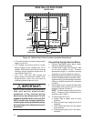
Single
Supply
(optional)
OR
Circuit A
Circuit B
GRD
GRD
Ground
Dual
Supply
60A
60A
ON
ON
OFF
OFF
Ground
Line
Voltage
Ground
Line
Voltage
60A
ON
OFF
CIRCUIT
BREAKERS
WHITE
RED
BLACK
BLACK
RED
WHITE
GREY
RED
YELLOW
BLACK
ORANGE
BLUE
YELLOW
RED
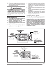
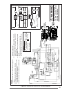
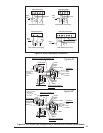
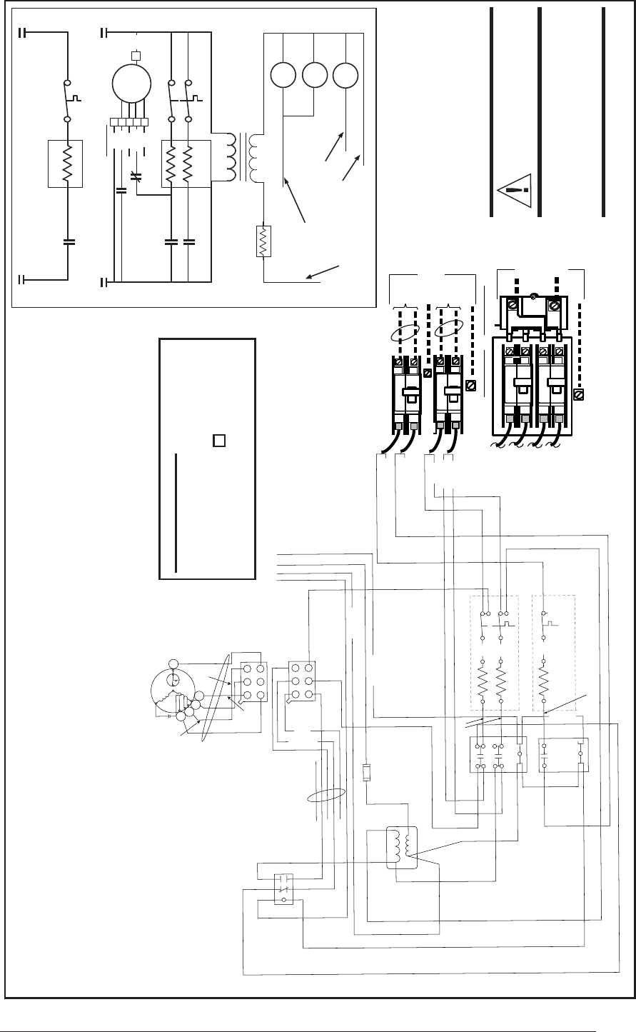
WARNING:
Switch circuit breakers to
the OFF position before
servicing the furnace.
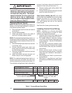
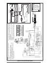
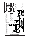
Figure 28. E3EB 015H, E3EB 017H Wiring Diagrams
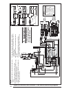
NOTES:
1) See unit data label for recommended supply wire
sizes.
2) Thermostat anticipator setting: 0.40 Amps.
3) To change blower speed on units without a relay
box refer to installation instructions.
4) Refer to furnace and/or relay box installation for
thermostat connections.
5) If any wire in this unit is to be replaced it must be
replaced with 105°C thermoplastic copper wire of
the same gauge.
6) Not suitable for use on systems exceeding 120V to
ground.
7) This wire is used with some accessories. See
accessory Installation Instructions for further de-
Legend:
CB – Circuit Breaker
E – Heater Element
IFR – Fan Relay
Cont – Contactor
LS – Limit Switch
IFM – Fan Motor
– Fan Plug
240V
Cont 1
C
H
L
IFM
CB-A
CB-A
CB-B
CB-B
Transformer
LS
Btm -
5.0/5.4
Top -
10.0/10.8
ML
MH
1
2
3
4
5
IFR
Red
Yellow
Blue
E
Cont 1
IFR
Cont 2
LS
Cont
2
Cont
1
24V
Red Pig-Tail
White Pig-Tail
IFR
Green Pig-Tail
Grey Pig-Tail
6
Black
Grey
Org.
White Jumper Wire
(See note 7)
E
Fuse