


17
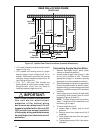
3. Install 240V supply circuit(s) and 24V wir-
ing to closet (see Figure 16 for appropriate
locations).
4. Position optional coil cabinet over fl oor cutout
and secure with three or more fasteners.
5. Position furnace onto coil cabinet and secure
with two or more fasteners.
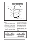
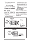
6. Use optional upfl ow duct connector or fi eld
supplied connector to attach furnace to
overhead supply duct (see Figure 17).
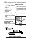
ELECTRICAL SYSTEM
INSTALLATION
WARNING:
To avoid the risk of electrical shock,
personal injury or death, disconnect
all electrical power to the unit before
performing any maintenance or
service. The unit may have more than
one electrical power supply.
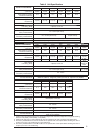
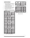
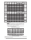
Codes, Specifi cations, and Re-
quirements
The wiring, installation, and electrical hookup
of this furnace must comply with the National
Electrical Code (or the Canadian Electrical Code)
and all regulations of local authorities having
jurisdiction. See Table 9a & 9b for minimum circuit
ampacity, maximum over-current protection, and
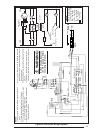
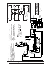
recommended wire size. See the unit wiring
diagram for other wiring details.
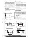
Supply-circuit requirements are as follows:
Applications and Furnace
Installation
NOTE: Remove refrigerant line knockouts in
furnace only when installing indoor coil of an
air conditioning or heat pump system.
Refer to instructions supplied with accessory
equipment.
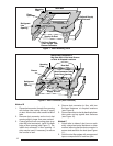
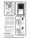
Over-the-Floor Return Air System
(Non-Ducted)
1. If fl oor underneath furnace is made of com-
bustible material, locate a pan fabricated of
non-combustible material with 1” upturned
fl anges under furnace return air opening (see
Figure 18).
2. Use optional upfl ow stand with fi lters or con-
struct a suitably braced mounting platform
in closet (see Figure 17 or 18).
3. Install 240V supply circuit(s) and 24V wir-
ing to closet (see Figure 16 for appropriate
locations).
4. Position optional coil cabinet onto upfl ow
stand or mounting platform and secure with
three or more fasteners.
5. Position furnace in upfl ow mode onto coil cabi-
net and secure with two or more fasteners.
6. Use optional upfl ow duct connector or fi eld
supplied connector to attach furnace to
overhead supply duct. (see Figure 17)
7. Install return air grille in closet preferably
at same level as upfl ow stand or below
mounting platform (see Figure 18).
NOTE: Be certain to provide an adequate free
return air area as described under Return Air
Codes and Requirements and Closed-Off Space
Requirements.
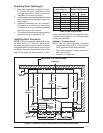
Through-the-Floor Return Air System
(Ducted)
1. Prepare Floor Opening(s):
a. Mark fl oor opening(s) as shown in Figure
19. Provide minimum clearances at rear
and left side walls of closet for installation
of furnace and wiring.
b. Cut fl oor opening on outside edge of
marked line so that opening is slightly
larger than area marked.
c. Additional provisions may be necessary
for optional air conditioning if refrigerant
lines are installed other than at the front
of the furnace.
2. If return air duct is made of combustible
material, locate a pan fabricated of non-
combustible material with 1” upturned
fl anges under furnace return air opening.
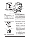
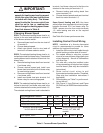
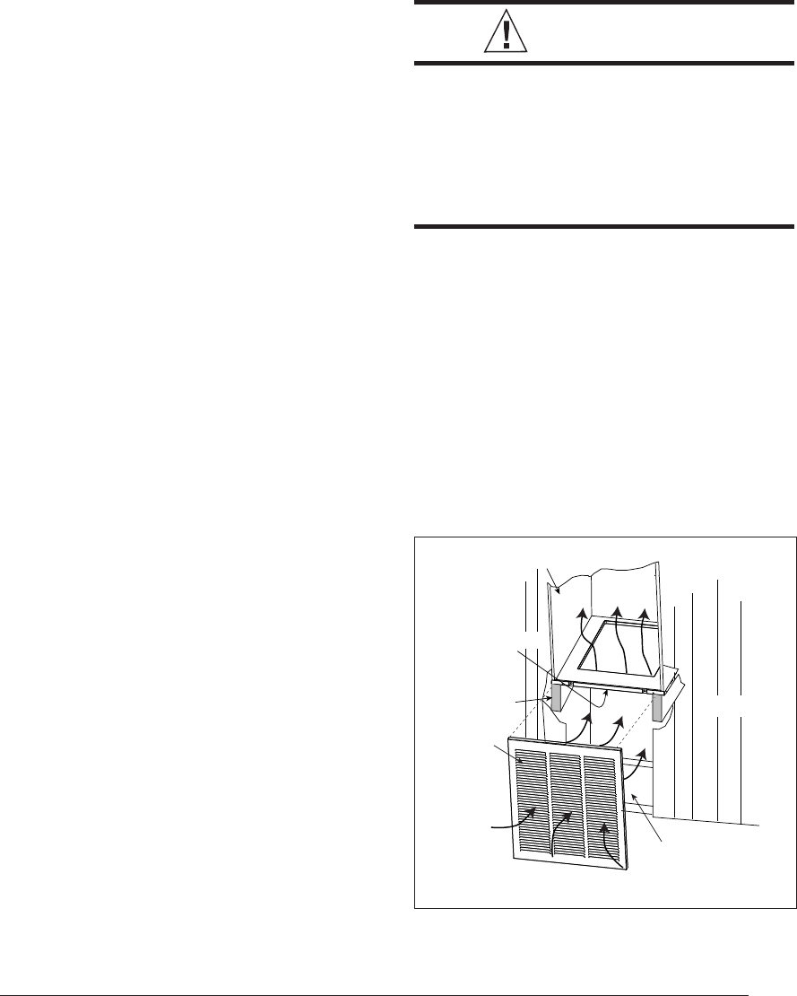
Figure 18. Over-the-Floor Return Air
System
Coil Cabinet
Air Filter
Braced
Mounting
Platform
Front
Grille
Non-combustible
Pan or
Enclosure
WALL
FLOOR