


11
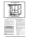
Preparing Floor Opening(s)
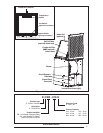
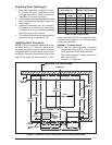
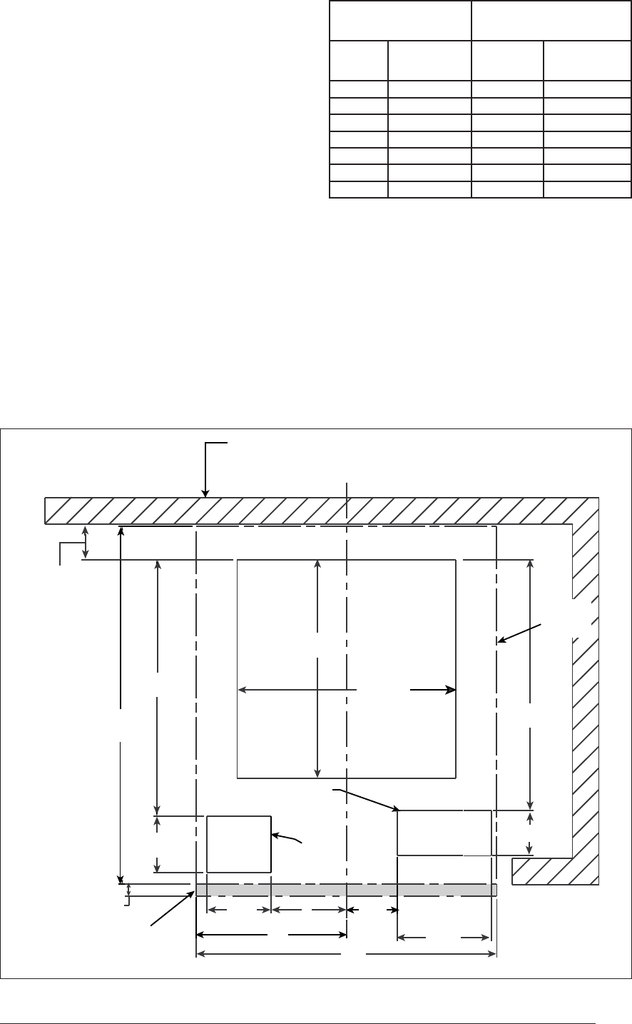
1. Mark fl oor opening(s) as shown in Figure
6. Provide minimum clearances at rear
and right side walls of closet or alcove for
installation of furnace and wiring.
2. Cut fl oor opening on outside edge of marked
line so that opening is slightly larger than
area marked.
3. Additional provisions may be necessary
for optional air conditioning or heat pump
if refrigerant lines are installed elsewhere
than at the front of the furnace.
4. The refrigerant and entrance supply opening
dimensions may be adjusted ± 1/2”.
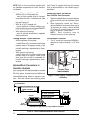
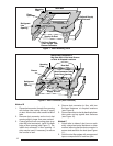
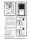
Installing Duct Connector
NOTE: The duct connector is designed for use
on ducts down to 12” wide. On typical ducts,
the fi nger tab duct connector may be installed
using Method B. On narrow ducts, there may be
insuffi cient clearance to bend the tabs on two
sides of the fi nger tab duct connector. In such
cases, use Method C or D. For screw down duct
connector use method E. For Platinum models
always use method A.
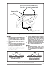
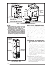
Method A - Platinum Series
NOTE: Flex duct used must have a minimum
temperature rating of 200
° F and meet all
other applicable codes and standards.
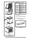
1. Place duct connector through opening in
fl oor. See Figure 9.
2. Connect 14” supply duct.
2-3/8" MIN
(60 mm)
"
6-1/4
23-3/4"
(603 mm)
20
"
3/4"
"10
14-1/2"
(368 mm)
3" (76 mm)
"4-1/4 "5
"3-3/8
REAR WALL OF ENCLOSURE
Furnace Outer
Door
Optional Supply Wire
Entrance
Optional
Refrigerant
Line
(Not required
for Platinum)
Center Line
17"
(432 mm)
14-1/2"
(368 mm)
16-5/8"
(422 mm)
(254 mm)
(86 mm)
(127 mm)
(108 mm)
(159 mm)
(19 mm)
(508 mm)
3-3/4"
(95 mm)
Furnace
Outline
A/C Or HP
Figure 6. Downfl ow Floor Cutout Locations (nominal dimensions)
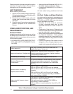
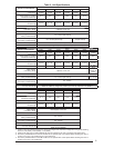
Table 4. Floor Cavity Sizes
If "X"
fl oor cavity is:
Use Duct Connector
Model Part Number
English
Metric
(mm)
Finger
Tab
Screw
Down
7/8" 22 901987 904008
2" 51 901988 904009
4 1/4" 108 901989 904010
6 1/4" 159 901990 904011
8 1/4" 210 901991 904012
10 1/4" 260 901992 904013
12 1/4" 311 901993 904014