


W415-0616 / B / 02.18.08
23
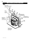
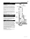
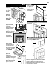
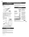
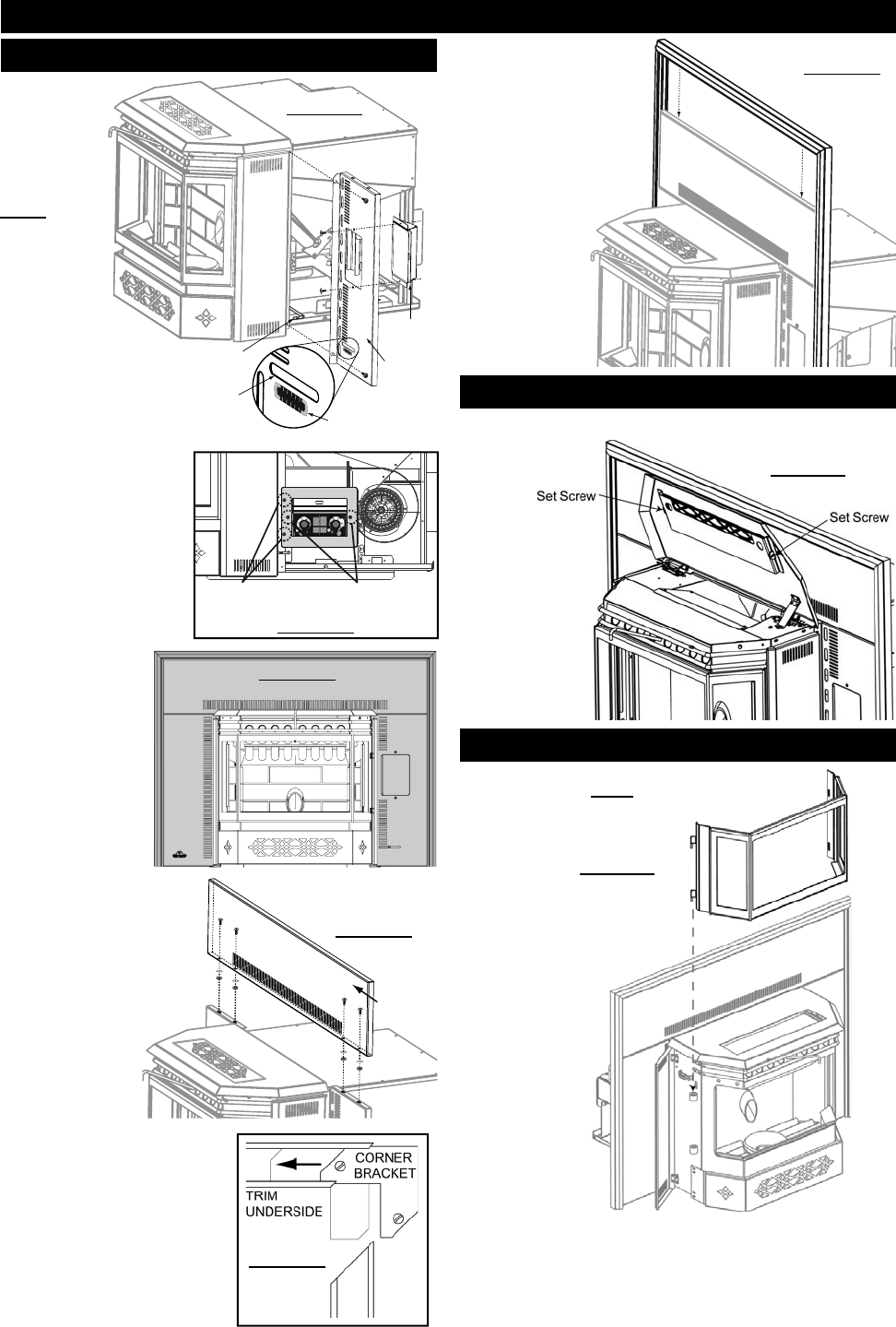
1. Secure the
Right Flashing
to the right
side of the
unit using two
of the #8 x
1/2" screws.
NOTE: Feed
the Air
Control Rod
into the Air
Control Slot
on the Right
Flashing
before securing.
(FIGURE 26)
2. Twist spring handle
(supplied with the heater)
onto the air control rod until
it hits the stop.
3. Remove the two control
panel securing screws,
discard the screws and
shipping bracket. (FIGURE
27)
4. Secure the control panel
to the Right Flashing using
the two #8 x 3/8"
screws. (FIGURE
20) Secure the Left
Flashing with the
remaining #8 x 1/2"
screws. (FIGURE
26)
NPI40 FINISHING
FIGURE 26
CONTROL
PANEL
AIR
CONTROL
ROD
AIR
CONTROL
SLOT
RIGHT
FLASHING
BURN
RATE LABEL
L
O
W
H
I
GH
1
2
3
4
5
L
O
W
H
I
G
H
1
2
3
4
5
FIGURE 27
PUSH TO START / POUSSEE POUR COMMENCER
5
3
1
2
4
OPTIMUM
1
3
5
4
2
SHIPPING
BRACKET
SECURING
SCREWS
CONTROL
PANEL
SECURING
SCREWS
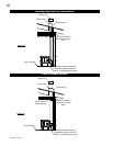
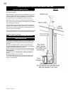
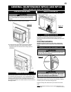
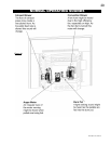
7. Slide the assembled
trim down over the
fl ashing. (FIGURE 31)
8. Affi x the logo to the
bottom left hand corner
of the left fl ashing.
TRIM
ASSEMBLY
TOP
FLASHING
FIGURE 29
FIGURE 30
FIGURE 31
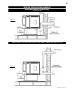
FLASHING INSTALLATION
FIGURE 28
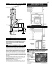
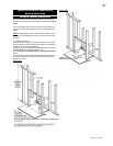
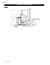
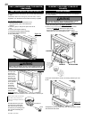
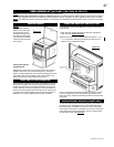
INSTALL VIEWING DOOR NPS40 AND NPI40
Figure 33
(Insert
Illustrated)
The main viewing door has been boxed separate
from the heater, but MUST be installed
before burning the heater.
1. Open both side panels, exposing the bushing on the left and
the latches on the right.
2. Align the pins on the door to the bushing on the left side of
the heater. Lower into place until both bushings touch.
3. Engage the latch hooks into the door frame. Snap the rear
handle hook to lock the latch closed.
TRIVET NPI40
The trivet for the NPI40 is attached by two set screws on the inside
of the hopper lid.
Figure 32
5. Align the holes
in the top of the Right and
Left Flashing with those on
the bottom lip of the Top
Flashing and secure from
the rear using the four #8-32
x 3/8" screws, washers and
nuts. (FIGURE 29)
6. The three
pieces of trim are
assembled in the
same manner as
a picture frame. Place the corner
brackets (with screw loosened)
into the trim sections. Tighten the
screw spreading the two pieces
apart. Attach the adjoining section.
Repeat with the opposite side.
Tighten all screws fi rmly.
(FIGURE 30)