


W415-0616 / B / 02.18.08
17
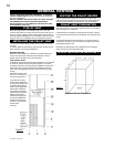
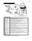
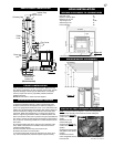
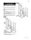
Figure 17
HEARTH MOUNT INSTALLATION
Floor
Protection
6”
MIN
Clean-out
tee
Outside Air
(Recommended)
Storm Collar
Vertical Cap
Chimney Cap
Bring outside air
to the stove
Pellet
Liner
Flue Cover
Pellet
Vent
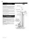
Clean all ashes out of the inside of the fi replace. Make sure that
the chimney and fi replace are free of cracks, loose mortar, cresote
deposits, blockage or other signs of deterioration. If necessary,
have any repair work done by a qualifi ed professional before
installing the insert.
Do not remove bricks or mortar from the fi replace.
1. Remove the fi replace damper or fasten it permanently open.
2. Measure the throat of the fi replace and mark this shape on a
piece of 24 gauge sheet metal (fl ue cover). Cut a hole sized for the
pellet liner to lie directly below the fi replace fl ue opening. Allow two
inches of material for a fl ange on all sides and cut to these mea-
surements. Bend down the fl anges. If you have never done this
before, it might be a good idea to make a cardboard pattern and
test it fi rst. fasten this fl ue cover in position as high as possible with
two masonry screws per side through the fl anges into the fi replace.
3. If you plan on connecting outside air it is recommended to do so
at this time.
4. Connect the pellet vent with a clean out tee to the back of the
stove. Refer to manufacturer's installation instructions and the
"General Venting Section".
5. Run a liner down the chimney and connect to tee.
6. Position the stove in it's fi nal location.
7. Pull the excess length of liner out through the top of the chim-
ney. Trim the excess liner, install the cap and cap the chimney.
PRIOR TO INSTALLATION
INSTALLATION INTO A MASONRY FIREPLACE
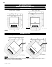
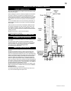
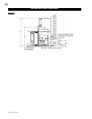
MINIMUM CLEARANCES TO COMBUSTIBLES
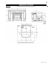
NPI40 INSTALLATION
Side wall to unit 8"
Maximum mantel depth 10"
Mantel to top of unit 8"
Top facing to unit 6 3/8"
Side facing to unit 6"
Floor protection* 6"*
* Floor Protection: Minimum 6" in front of door and to either side.
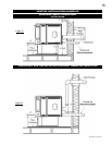
MINIMUM MANTEL CLEARANCES
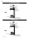
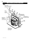
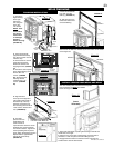
REAR TO TOP VENT CONVERSION INSTRUCTIONS
NOTE: The insert is factory shipped in a rear vent confi guration.
1. To vent exit vertically, remove the two screws holding the
exhaust cover. NOTE: Be
careful not to damage the
gasket.
2. Remove the two
screws holding the
exhaust tube (NOTE: Be
careful not to damage the
gasket).
3. Attach the exhaust tube
and gasket in the vertical
position.
4. Attach the exhaust
cover and gasket over the
horizontal exit.
Figure 18
Exhaust Tube
Exhaust Cover
Figure 20
Figure 19