


26
W415-0299 / C / 03.12.03
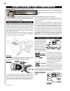
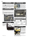
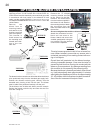
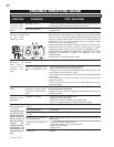
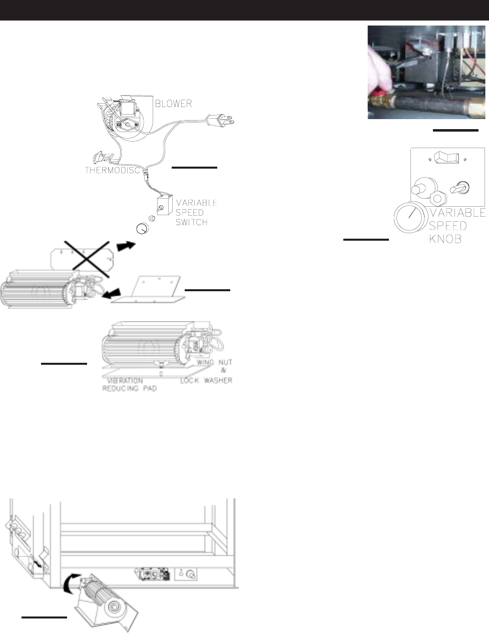
Remove the "Z" shaped
mounting bracket secured
to the burner, by the pilot.
Remove the thermodisc
from the bracket supplied in
the blower kit and attach to
the mounting bracket. Attach
the connectors from the
black and white wires to the
thermodisc.
Do not overtighten thermodisc or distort housing.
Attach the connectors from the
black and red wires to the
blower. Attach and secure the
variable speed switch using the
nut provided. Plug the harness
cord into the receptacle.
The wire harness provided in this kit is a universal har-
ness. When installed, ensure that any excess wire is
contained, preventing it from making contact with mov-
ing or hot objects.
Drywall dust will penetrate into the blower bearings,
causing irreparable damage. Care must be taken to
prevent drywall dust from coming into contact with the
blower or its compartment. Any damage resulting from
this condition is not covered by the warranty policy.
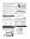
Because the blower is thermally activated, when turned
on, it will automatically start approximately 10 minutes
after lighting the fireplace and will run for approximately
30 - 45 minutes after the fireplace has been turned off.
Use of the fan increases the output of heat.
INSTALLATION TO BE DONE BY A QUALIFIED IN-
STALLER and must be electrically connected and grounded
in accordance with local codes. In the absence of local
codes, use the current CSA C22.1 CANADIAN ELECTRICAL CODE
in Canada or the ANSI/NFPA 70 NATIONAL ELECTRICAL CODE in the
United States.
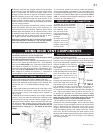
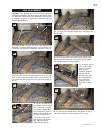
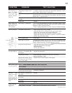
Remove the
blower from its
mounting bracket
and attach to the
bracket supplied
with the fireplace.
This bracket is
found secured on
the mounting stud
located at the bot-
tom of the vent
side wall.
r
e
d
w
h
i
t
e
b
l
a
c
k
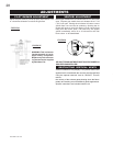
Position the vibration reducing pad, centred, onto the
threaded stud, piercing a hole into the pad. The blower
must be able to be positioned entirely onto the pad.
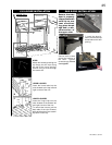
Tilt the blower onto its side and slide it past the controls.
Position the blower under the clip and onto the stud. Se-
cure with a wing nut.
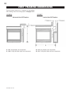
FIGURE 61
FIGURE 58
FIGURE 60
FIGURE 62
FIGURE 63
FIGURE 59
The blower bracket contains two holes that allow the blower
to be positioned away from the intended gas supply hole.
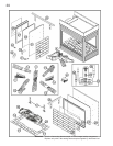
OPTIONAL BLOWER INSTALLATION