


22
W415-0299 / C / 03.12.03
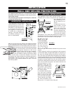
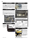
Do not connect either the wall switch, thermostat or
gas valve to electricity (110 volts).
Attach the two leads to terminals 1 and 3 located on the
gas valve.
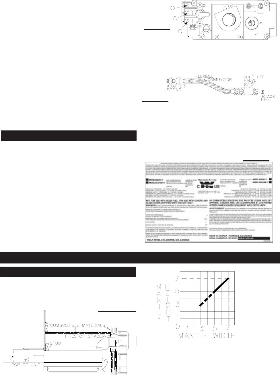
4. Install the rigid black pipe, ½" type-L copper tubing or,
if local codes permit, a
3
/
8
" flex connector and shutoff valve
to the gas line and the fireplace gas valve. Seal and tighten
securely. An adapter fitting is required between the gas
valve and the copper tubing or flex connector.
Do not kink flexible connector.
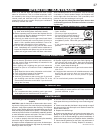
5. Check for gas leaks by brushing on a soap and water
solution.
Do not use open flame.
6. Mark the appropriate boxes on the rating plate label to
indicate the model type.
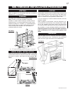
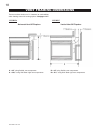
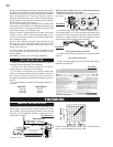
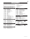
Combustible mantle clearance can vary according to the
mantle depth. Use the graph to help evaluate the clear-
ance needed. The three-sided top extension piece may be
removed if non-combustible framing is faced with a non-
combustible material.
FIGURES 45 a-b
Dashed lines are suitable mantle sizes and clearances
when a non-combustible facing is used.
*
SEE FIGURE 16.
P
I
P
I
3
1
2
L
O
T
N
O
L
O
T
H
I
L
O
F
F
O
FIGURE 42
FIGURE 44
TOP OF THE UNIT
TOP EXTENTION
7" MANTLE
3" MANTLE
*
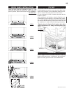
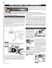
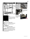
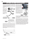
8. Apply a heavy bead of waterproof caulking 2 inches above
the flashing. Slide the storm collar around the air terminal
and down to the caulking. Tighten to ensure that a weather-
tight seal between the air terminal and the collar is
achieved. Attach the other storm collar centered between
the air intake and air exhaust slots onto the air terminal.
Tighten securely. Attach the rain cap.
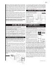
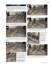
8. Continue adding rigid venting sections, sealing and
securing as above. Attach a 5" collapsed telescopic pipe
to the last section of rigid piping. Secure with screws and
seal. Repeat using a 8" telescopic pipe.
9. Run a bead of high temperature sealant around the
outside of the 5" elbow. Pull the adjustable pipe a mini-
mum 2" onto the elbow. Secure with 3 screws. Repeat with
the 8" telescopic pipe.
10. In the attic, slide the vent pipe collar down to cover up
the open end of the shield and tighten. This will prevent
any materials, such as insulation, from filling up the 1" air
space around the pipe.
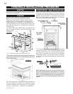
It is best to frame your fireplace after it is positioned and
the vent system is installed. Use 2x4's and frame to local
building codes.
See PAGE 14 for bar type / countertop installation.
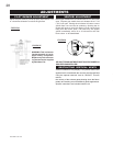
1. Move the fireplace into position and secure to the floor
using #10 hex head screws (not supplied).
2. Route a 3/8" N.P.T. black iron gas line, 1/2" type-L
copper tubing or equivalent to the fireplace.
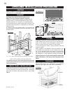
3. For ease of accessibility, an optional remote wall
switch or millivolt thermostat may be installed in a conven-
ient location. Route 2-strand (solid core) millivolt wire
through the electrical hole located at the bottom left side of
the unit.
The recommended maximum lead length depends on
wire size:
WIRE SIZE MAX. LENGTH
14 gauge 100 feet
16 gauge 60 feet
18 gauge 40 feet
FIGURE 43
GAS INSTALLATION
FINISHING
MANTLE INSTALLATION