


16
W415-0299 / C / 03.12.03
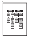
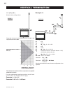
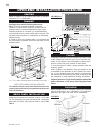
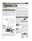
Refer to pages 6-13. All venting must have a minimum
clearance of 1" to combustible.
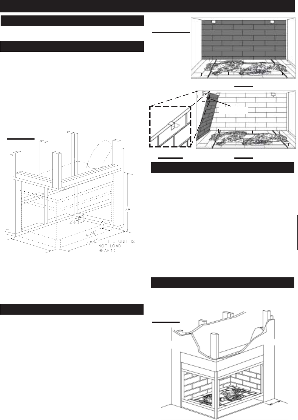
See Page 18 for additional framing dimensions.
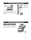
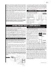
Note: In order to avoid the possibility of exposed
insulation or vapour barrier coming in contact with the
fireplace body, it is recommended that the walls of the
fireplace enclosure be “finished” (ie: drywall/sheetrock),
as you would finish any other outside wall of a home. This
will ensure that clearance to combustibles is maintained
within the cavity.
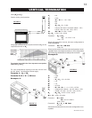
It is best to frame your fireplace after it is positioned and
the vent system is installed. Use 2x4's and frame to local
building codes.
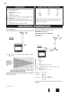
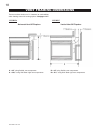
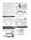
NOTE: LEFT CORNER UNIT ILLUSTRATED
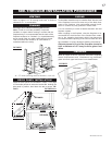
To install the fireplace face flush with the finished wall,
position the framework to accommodate the thickness
of the finished wall.
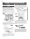
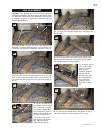
Install the base panels as illustrated in steps 1-4 on page
15. The side panel sits under the bracket tab. Holding the
side panel in position, bend down the tab to secure. DE-
TAIL 6.
A
A = 25¼" minus finishing material thickness each side.
FIGURES 21a-c
FIGURE 20
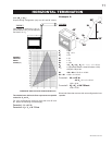
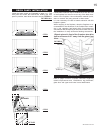
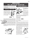
Combustible materials may be installed flush with the front
of the fireplace but must not cover any of the black face-
areas of the fireplace. Non-combustible material (brick,
stone or ceramic tile) may protrude in these areas.
It is not necessary to install a hearth extension with this
fireplace system.
When roughing in the fireplace, raise the fireplace to ac-
commodate for the thickness of the finished floor materi-
als, i.e. tile, carpeting, hard wood, which if not planned for
will interfere with the opening of the lower access door and
the installation of many decorative flashing accessories.
Objects placed in front of the fireplace should be
kept a minimum of 48" away from the glass front
faces.
Refer to pages 22-25 for complete instructions regarding
mantle requirements and installations, log placement,
glass door and upper and lower louvre attachments.
STEP 6
RETAINER
DETAIL 6
STEP 5
DRYWALL
5" MIN
DRYWALL
FIGURE 22
OPEN-END INSTALLATION PROCEDURE
BRICK PANEL INSTALLATION
VENTING
FRAMING
FACING
FINISHING