


22
W415-0153 / B / 06.10.10
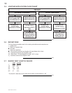
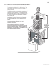
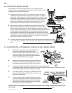
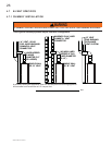
4.2.2 VERTICAL INSTALLATION
This application occurs when venting through a roof. Installation kits for
various roof pitches are available from your authorized dealer / distributor. See
accessories to order specifi c kits required.
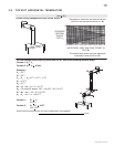
A. Determine the air terminal location, cut and frame a square opening as
illustrated in the ceiling and the roof to provide the minimum 1“ clearance
between the vent pipe and any combustible material. Try to center the vent
pipe location midway between two joists to prevent having to cut them. Use
a plumb bob to line up the center of the openings. A vent pipe shield will
prevent any materials such as insulation, from fi lling up the 1” air space
around the pipe. Nail headers between the joist for extra support.
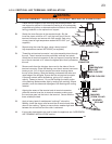
B. Apply a bead of caulking (not supplied) to the framework or to the Wolf
Steel vent pipe shield plate or equivalent (in the case of a fi nished ceiling),
and secure over the opening in the ceiling. A fi restop must be placed on the
bottom of each framed opening in a roof or ceiling that the venting system passes
through. Apply a bead of caulking all around and place a fi restop spacer over
the vent shield to restrict cold air from being drawn into the room or around the
fi replace. Ensure that both spacer and shield maintain the required clearance to
combustibles. Once the vent pipe is installed in its fi nal position, apply sealant
between the pipe and the fi restop assembly.
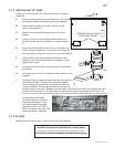
C. In the attic, slide the vent pipe collar down to cover up the open end of the shield and tighten.
This will prevent any materials, such as insulation, from fi lling up the 1” air space around the
pipe.
21.1
CAULKING
VENT PIPE
SHIELD
FIRESTOP
UNDERSIDE OF
JOIST
VENT
PIPE
COLLAR
VENT
PIPE
SHIELD
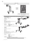
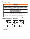
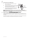
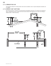
A. Stretch the inner fl ex pipe to the required length taking
into account the additional length needed for the
fi nished wall surface. Slip the vent pipe a minimum of 2”
over the inner sleeve of the air terminal and secure with
3 #8 screws. Apply a heavy bead of the high temperature
sealant W573-0007 Mill Pac (not supplied).
B. Using the outer rigid pipe, slide over the outer combustion air
sleeve of the air terminal and secure with 3 #8 screws. Seal
using high temperature sealant W573-0002 (not supplied).
C. Insert the vent pipes through the fi restop maintaining the required clearance to
combustibles. Holding the air terminal (lettering in an upright, readable position), secure to the exterior wall and
make weather tight by sealing with caulking (not supplied).
D. From inside the house, using silicone, seal between the vent
pipe and the fi restop. Then slide the black trim collar over the
vent pipe up to the fi restop.
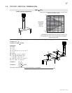
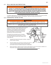
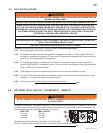
E. If more vent pipe needs to be used to reach the appliance,
couple them together as illustrated. The vent system must be
supported approximately every 3 feet for both vertical and
horizontal runs. Use noncombustible strapping to maintain
the minimum clearance to combustibles.
The air terminal mounting plate may be recessed into the exterior wall or siding no greater than the depth of its
return fl ange.
23.7A
SCREWS
#10x2"
SEALANT
HIGH TEMP
2" OVERLAP
PIPE
4"FLEX
CAULKING
PIPE
7" RIGID
#8 X 1/2” SELF DRILLING
SCREWS & WASHERS
INNER COUPLER
OUTER COUPLER
HI-TEMP
SEALANT
OUTER
RIGID PIPE
INNER
FLEX PIPE
OUTER
RIGID PIPE
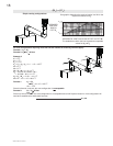
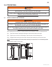
4.2.3 HORIZONTAL AIR TERMINAL INSTALLATION - MODEL GDS28
9"
9"