


9
W415-0547 / B / 05.08.06
Use only Wolf Steel, Simpson Dura-Vent, Selkirk Direct Temp
or American Metal Amerivent venting components.
For Simpson Dura-Vent, Selkirk Direct Temp and American
Metal Amerivent, follow the installation procedure provided
with the venting components.
All outer pipe joints of these venting systems must be sealed
using Red RTV High Temperature Sealant.
Wolf Steel, Simpson Dura-Vent, Selkirk Direct Temp and
American Metal Amerivent venting systems must not be
combined.
A starter adaptor must be used and may be purchased from
the corresponding supplier:
PART SUPPLIER
Duravent - GDS924N Wolf Steel
Amerivent - 4DSCB-N1 American Metal
Direct Temp - 4DT-AAN Selkirk
For vent systems that provide seals on the inner exhaust fl ue,
only the outer air intake joints must be sealed using a red high
temperature silicone (RTV). This same sealant maybe used
on both the inner exhaust and outer intake vent pipe joints
of all other approved vent systems except for the exhaust
vent pipe connection to the fi replace fl ue collar which must
be sealed using the black high temperature sealant Mill Pac.
High temperature sealant must be ordered separately.
When using Wolf Steel venting components, use only the
following vent kits: WALL TERMINAL KIT GD175 (7-1/2'
of venting included), WALL TERMINAL KIT GD176 (24" of
venting included), or 1/12 TO 7/12 PITCH ROOF TERMINAL
KIT GD110, 8/12 TO 12/12 ROOF TERMINAL KIT GD111,
FLAT ROOF TERMINAL KIT GD112 or STOVE PERISCOPE
KIT GD180 (for wall penetration below grade) in conjunction
with the appropriate venting components.
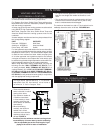
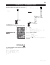
• These vent kits allow for
either horizontal or vertical
venting of the stove.
• The maximum number of
4" fl exible connections
is 3 horizontally or three
vertically (excluding the
stove and the air terminal
connections).
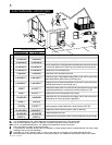
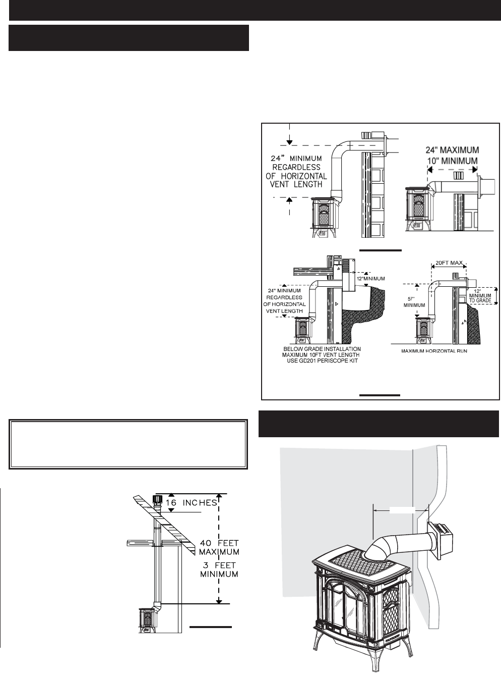
• When terminating
vertically, the minimum
vertical rise is 3 feet
above the stove and the
maximum vertical rise is
40 feet. FIGURE 4.
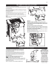
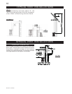
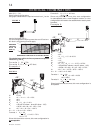
Deviation from the minimum vertical vent length can
create diffi culty in burner start-up and/or carboning.
Use an adjustable pipe as the fi nal length of rigid
piping to the stove for ease of installation.
FIGS 6a-b
FIGURE 5
HORIZONTAL RUN NOT TO
EXCEED VERTICAL RISE
• For optimum fl ame appearance and stove performance,
keep the vent length and number of elbows to a mini
mum.
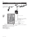
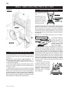
• The air terminal must remain unobstructed at all times.
Examine the air terminal at least once a year to verify
that it is unobstructed and undamaged.
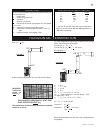
The maximum horizontal run with a 57 inch vertical rise im-
mediately above the stove is 20 feet . FIGURES 6a-b.
VENTING
VENTING LENGTHS &
AIR TERMINAL LOCATIONS
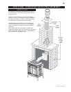
For optimum performance, it is recom-
mended that all horizontal runs have a
minimum ¼ inch rise per foot.
16 INCHES
3 FEET
MINIMUM
40 FEET
MAXIMUM
FIGURE 4
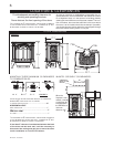
24” MAX
TYPICAL CORNER INSTALL
WITH ZERO RISE