


14
W415-0447 / B / 05.24.05
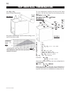
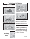
FIGURE 23
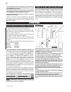
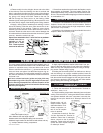
The vent system must be supported approximately every 3
feet for both vertical and horizontal runs. Use Wolf Steel vent
spacers or equivalent every 3 feet and either side of each
elbow to maintain the minimum 1¼" clearance between the
outer and inner vent pipes. Use Wolf Steel support ring as-
sembly or equivalent noncombustible strapping to maintain
the minimum clearance to combustibles for both vertical and
horizontal runs.
All inner exhaust and outer intake vent pipe joists may
be sealed using either Red RTV high temp silicone seal-
ant or Black high temp Mill Pac with the exception of the
fireplace exhaust flue collar which must be sealed using
Mill Pac (not supplied).
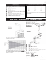
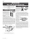
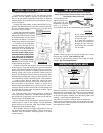
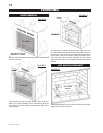
1. Move the fireplace into po-
sition. Measure the vent length required
between terminal and fireplace taking into account the
additional length needed for the finished wall surface and any
1¼" overlaps between venting components.
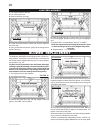
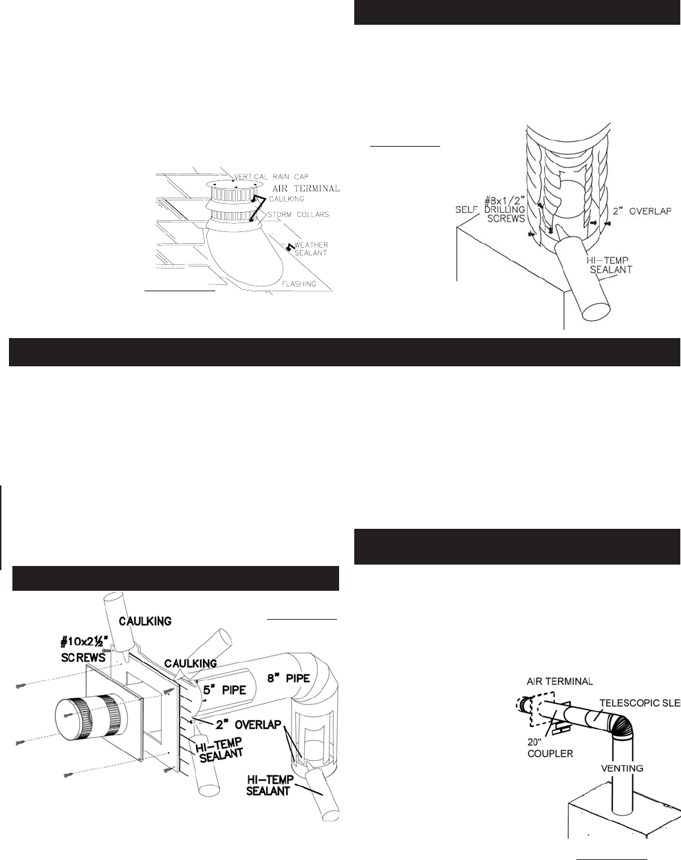
2. Apply high temperature sealant (W573-0007 not pro-
vided) to the outer edge of the 5" inner collar of the fireplace.
Attach the first vent component and secure using 3 self tap-
ping screws. Repeat using 8" piping.
3. Holding the air terminal (with the air deflectors to the top
and the lettering in an upright, readable position) insert the
terminal into both vent pipes with a twisting motion to ensure that
both the terminal sleeves engage into the vent pipes and seal-
ant. Secure the terminal to the exterior wall and make weather
tight by sealing with caulking (not supplied).
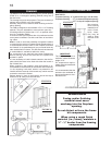
1. Follow the instructions for "Horizontal Air Terminal In-
stallations", items 1 to 3.
2. Continue adding components alternating inner and outer
venting. Ensure that all 5" venting and elbows have sufficient
vent spacers attached and each component is securely fas-
tened to the one prior. Attach the 5" telescopic sleeve to the
vent run.
Repeat using a 8" tel-
escopic sleeve. Secure
and seal as before. To fa-
cilitate completion, at-
tach 5" and 8" couplers
to the air terminal.
3. Install the air terminal. See item
3 of the Horizontal Air Terminal In-
stallation. Extend the 5" telescopic
sleeve; connect to the air terminal
assembly. Fasten with self tapping
screws and seal. Repeat using the
8" telescopic sleeve.
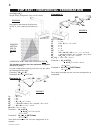
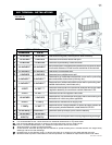
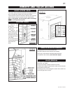
FIGURE 24
5. Remove nails from the shingles, above and to the sides
of the chimney. Place the flashing over the air terminal and
slide it underneath the sides and upper edge of the shingles.
Ensure that the air terminal is properly centred within the flash-
ing, giving a 3/4" margin all around. Fasten to the roof. Do
not nail through the lower portion of the flashing. Make
weather-tight by sealing with caulking. Where possible, cover
the sides and top edges of the flashing with roofing material.
6. Apply a heavy bead of weatherproof caulking 2 inches
above the flashing. Slide the storm collar around the air ter-
minal and down to the caulking. Tighten to ensure that a
weather-tight seal between the air terminal and the collar is
achieved. Attach the other storm collar centred between the
air intake and the air exhaust slots onto the air terminal. Tighten
securely. Attach the vertical rain cap.
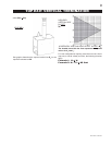
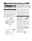
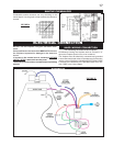
Spacers are attached to the 5" inner flex liner at predeter-
mined intervals to
maintain a 1-1/4" air
gap to the 8" outer
liner. These spacers
must not be removed.
FIGURE 21
7. If more liner needs to be used to reach the fireplace, couple
them together as illustrated. The vent system must be sup-
ported approximately every 3 feet for both vertical and horizon-
tal runs. Use noncombustible strapping to maintain a clearance
to combustibles of 1".
1. Install the 5 inch diameter aluminium flexible liner to the
fireplace. Secure with 3 screws and flat washers. Seal the
joint and screw holes using the high temperature sealant
(W573-0007 not provided).
2. Install the 8 inch diameter aluminium flexible liner to the
fireplace. Attach and seal the joints.
FIREPLACE VENT CONNECTION
USING RIGID VENT COMPONENTS
HORIZONTAL AIR TERMINAL INSTALLATION
EXTENDED HORIZONTAL AIR TERMINAL
INSTALLATION
FIGURE 22