


12
W415-0447 / B / 05.24.05
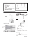
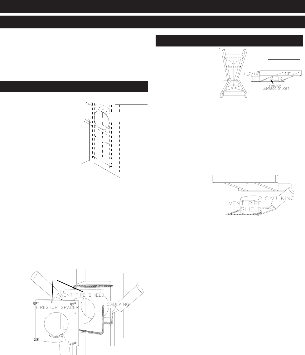
ROUND OR
SQUARE HOLE
12.500"
16.000"
c
/c
14
7
/
16
"
13"
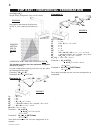
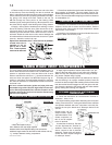
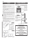
FIGURE 13
This application occurs when
venting through an exterior
wall. Having determined the air
terminal location, cut and frame
a hole in an exterior wall. The
recommended framed opening
is 14
7
/16" W x 13" H with a mini-
mum 12
1
/2" round or square
opening inside a finished wall.
See figure15.
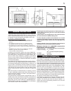
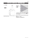
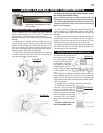
1. Mark and cut the vent pipe
shield to the determined depth of
the combustible wall. Apply a bead of
caulking (not supplied) to the framework or
to the shield plate (in the case of a finished wall) and secure
the shield through the opening to the interior wall. The final
location of the vent pipe shield should maintain the required
clearance to the 8" vent pipe / liner. (See note above). Do not
fill this cavity with any type of material. Apply a bead of caulk-
ing all around and place a firestop spacer over the vent shield
to restrict cold air from being drawn into the room or around
the fireplace. Ensure that both spacer and shield maintain
the required clearance to combustibles. Once the vent
pipe / liner is installed in its final position, apply sealant be-
tween the pipe / liner and the firestop spacer.
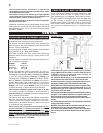
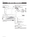
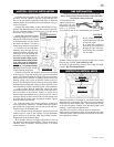
This application occurs
when venting through a
roof. Installation kits for
various roof pitches are
available from your Napo-
leon dealer. See Acces-
sories to order the spe-
cific kit required.
1. Determine the air terminal location, cut and frame
14
7
/
16
" W x 13" H openings in the ceiling and the roof to pro-
vide the minimum 2 inch clearance between the fireplace
pipe / liner and any combustible material. Try to centre the
exhaust pipe location midway between two joist to prevent
having to cut them. Use a plumb bob to line up the centre of
the openings. DO NOT FILL THIS SPACE WITH ANY TYPE
OF MATERIAL.
A vent pipe
shield will prevent
any materials such
as insulation, from
filling up the 1" air
space around the
pipe. Nail headers
between the joist
for extra support.
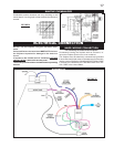
2. Apply a bead of caulking (not supplied) to the frame-
work or to the Wolf Steel vent pipe shield plate or equivalent
(in the case of a finished ceiling), and secure over the open-
ing in the ceiling. A firestop must be placed on the bottom of
each framed opening in a roof or ceiling that the venting sys-
tem passes through. Apply a bead of caulking all around
and place a firestop spacer over the vent shield to restrict
cold air from being drawn into the room or around the fire-
place. Ensure that both spacer and shield maintain the re-
quired clearance to combustibles. Once the vent pipe / liner
is installed in its final position, apply sealant between the pipe
/ liner and the firestop spacer.
FIGURE 16
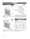
FIGURE 14
OR
HORIZONTAL INSTALLATION
VERTICAL INSTALLATION
FIGURE 15
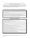
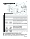
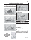
INSTALLATION
WALL AND CEILING PROTECTION
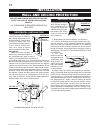
FOR SAFE AND PROPER OPERATION OF THE FIRE-
PLACE, FOLLOW THE VENTING INSTRUCTIONS
EXACTLY.
A 2” CLEARANCE IS REQUIRED AROUND THE
VENT PIPE.
SHOWN FROM INSIDE THE STRUCTURE