


9
W415-0512 / D / 07.16.08
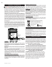
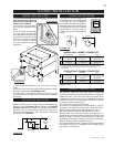
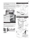
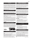
3. The access panel can be removed by taking out the 8
#10 self taping screws. A 5/16” nut driver will be required to
complete this job. Unplug wires from the thermal switch on
the panel. See FIGURE 15.
4. Remove the securing wingnut from the blower mounting
bracket, slide the bracket to the right and rotate the left side
of the assembly out of the cavity to clear the blower motor.
Disconnect the two wires from the blower motor. Remove
the ground wire from the blower mounting bracket, then the
assembly can be taken out of the rear cavity through the
access door opening.
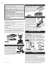
5. Remove the 3 screws that hold the blower to the mounting
bracket. Service or replace the blower as required.
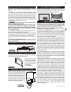
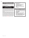
6. Reinstall the blower assem-
bly making sure the blower
bracket is seated under the
securing tab. FIGURE 16.
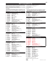
Reattach the wire connectors.
FIGURE 17.
7. Replace the gasket on the
access door. To replace the
access panel, reverse Step
3 .
8. Replace the bricks into the
fi rebox. Reinstall the door.
1. Turn off all electrical power to the insert. Remove the glass
door and set aside in a safe place.
2. Remove the two screws from the outer edge of the side
panel(s).
3. Push the side panel toward the door and pull away from
the insert, releasing the panel from the keyed slot.
4. Service or replace the blower(s) as required.
5. Re-install the side panel(s) by reversing the procedure.
FIGURE 16
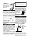
HEAT
SENSOR
RHEOSTAT
G
B
W
BLOWER
BLOWER
FIGURE 18
SECURING
TAB
WINGNUT
GROUND STUD
1402 BLOWER SERVICE OR REPLACEMENT
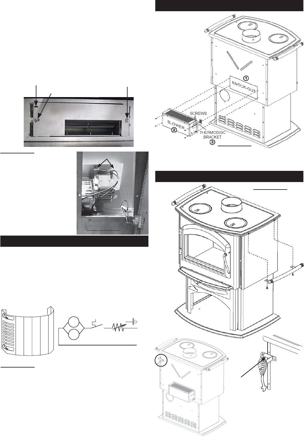
1150 BLOWER INSTALLATION
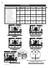
1150 FEATURES
FIGURE 20
Wood
Storage
(intended for
short term use)
Pot
Fender
FIGURE 19
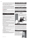
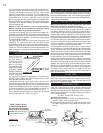
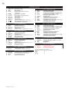
1. Remove the knock-
out from the back of
the fi replace.
2. Install the blow-
er and housing as
shown using the 4
screws supplied.
3. Loosen the thermodisc bracket (2 screws) and slide the
bracket forward until the thermodisc is touching the rear
fi rebox and secure.
Remove the screw, as illustrated,
from the preferred side of the stove
rear. Secure the lid lifter hook, as
illustrated, facing out to the side, or
bend it towards the back.
LID LIFTER
HOOK
WIRES
FIGURE 17