


8
W415-0512 / D / 07.16.08
In the United States: While it is not required, it is recom-
mended that a chimney liner be installed that is continuous
from the insert to the top of the chimney, particularly when the
insert is installed in a basement. For this type of connection,
use the “In Canada” installation instructions above.
In the United States, continued:
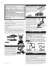
If a continuous liner is not installed, a “direct fl ue connec-
tion” must be made. The direct fl ue connection requires a
non-combustible connector that extends from the insert into
the chimney fl ue liner and also that the installed fl ue cover
be sealed below the entry point of the connector to prevent
dilution of combustion products in the chimney fl ue with air
from inside the house. Cap the top of the chimney using an
approved rain cap.
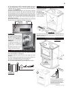
1402 INSERT MODEL
An optional low clearance fl ue connector is available to fa-
cilitate hook up into a tight fi tting fi replace. Consult your local
dealer for details.
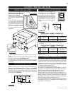
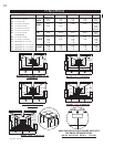
The following installation requirements must be observed
when installing solid fuel burning inserts into factory built
fi replaces.
1. The factory built fi replace must be listed per UL 127 or
ULC S610.
2. Clearances to any combustible material surrounding this
insert as identifi ed in Figure 10 must be followed. These clear-
ance requirements supersede any pre-existing facing material
clearances listed for the factory built fi replace.
3. Installation must include a full height listed chimney liner
meeting HT requirements (2100°F) per 1777 (U.S.) or ULC
S635 (Canada). The liner must be securely attached to the
insert fl ue collar and the chimney top.
4. Means must be provided to prevent room air passage to the
chimney cavity of the fi replace. This may be accomplished by
sealing the damper area around the chimney liner, or sealing
the fi replace front.
5. The air fl ow within and around the fi replace shall not be
altered by the installation of the insert (i.e. no louvres or cool-
ing air inlet or outlet ports are blocked), unless specifi cally
tested as such for each factory built fi replace manufacturer
and model line. (Note - using a louvred face plate (surround)
complies with this requirement)
6. Alteration of the fi replace in any manner is not permitted
with the following exceptions;
a. external trim pieces which do not affect the operation
of the fi replace may be removed providing they can be
stored on or within the fi replace for reassembly if the insert
is removed.
b. the chimney damper may be removed to install the
chimney liner.
7. Circulating air chambers (i.e. in a steel fi replace liner or
metal heat circulator) shall not be blocked.
8. Means must be provided for removal of the insert to clean
the chimney fl ue.
9. Inserts that project in front of the fi replace must be supplied
with appropriate support means.
10. A permanent metal warning label must be attached to the
back of the fi replace stating that the fi replace must be restored
to its original condition for safe use without the insert.
Drywall dust will penetrate into the blower bearings,
causing irreparable damage. Care must be taken to
prevent drywall dust from coming into contact with the
blower or its compartment. Any damage resulting from
this condition is not covered by the warranty policy.
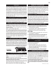
Use of the blower increases the output of
heat.
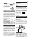
Provisions have been made on the stove to install an optional
blower kit (EP62-1) that comes complete with a variable speed
switch to turn the blower on and off, as well as adjusting the
blower speed. An optional thermostatic sensor control kit,
EP36, to thermally activate the blower is also available.
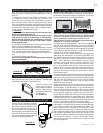
NOTE: if the optional blower (EP62-1) is installed, the
blower guard (W320-0011) must be installed. This guard
is available from your Napoleon dealer.
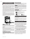
Attach the mounting bracket to the blower
assembly. Then attach the mounting
bracket to the back of your stove, push
on the variable speed knob and plug into
any grounded electrical outlet.
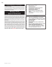
The
1402 inserts comes equipped with two blowers, while the
1101 has one blower. These blowers are thermally activated.
Depending on the intensity of the fi re, the blowers will start
15-30 minutes after lighting. The heat sensor for the 1402 is
located on the right hand side of the unit and the 1101 has a
heat sensor located at the back on the blower access door.
When fi rst starting the fi re, the sensor may be impeded by
a large log or an unevenly burning fi re, causing the blowers
to cycle on and off. To control this, either build your fi re up
evenly or turn down the blowers until the right side of the
fi rebox is hot.
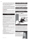
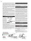
1. Turn off all electrical power to the
insert. Remove the glass door and
set aside in a safe place.
2. Remove the top right side bricks
from inside the fi rebox, 4-#7’s and
2-#2’s. Then remove the rest of the
side and back bricks from the right
side of the 1101 insert. It is not neces-
sary to remove the bottom bricks.
MOUNTING
BRACKET
BLOWER GUARD
FIGURE 14
INSTALLATION INTO A FACTORY BUILT
FIREPLACE
STOVE MODELS
OPTIONAL BLOWER
LEG MODELS ONLY
INSERT MODELS
1101 BLOWER SERVICE OR REPLACEMENT
VARIABLE
SPEED
SWITCH
GASKET
THERMAL
SWITCH
FIGURE 15
BLOWER
ASSEMBLY