


7
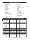
W415-0512 / D / 07.16.08
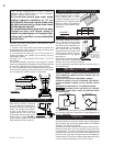
It must be installed between ceil-
ing joists, with radiation shield
and roof flashing, so that the
structural strength, insulation and
waterproof qualities of the home
are not lessened. Seal with sili-
cone to maintain a vapour barrier
at the chimney and outside air
pipe penetrations.
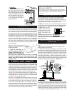
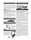
Connection from the stove’s air intake to the outside is manda-
tory in mobile homes only, either through a hole in the wall to
line up with the knockout in the pedestal back, or through a
hole in the fl oor to line up with the hole in the pedestal base.
Use a fresh air kit. Secure the 4 inch diameter aluminum liner
by fl aring the end once it is inserted through the 4-1/2 inch
diameter hole in either the back or base of the pedestal. If the
air intake is through the fl oor, the hole in the pedestal back
must be covered with sheet metal to avoid cold air spillage
into the room. A cover plate is available from your Wolf Steel
Ltd. dealer. Avoid cutting away fl oor joists, wall studs, electrical
wires or plumbing. Seal around the outside pipe with insulation
to prevent drafts.
Attach the rear knockout plate
(located inside the ash pan for
shipping purposes).
If room air starvation oc-
curs because the fresh air
intake is blocked with ice,
leaves, etc., or because
the stove door was left open, or due to a strong
exhaust fan operating etc., dangerous fumes and
smoke from the operating stove could be drawn
into the room.
Your EPI 1101 and 1402 insert fi rebox is the exact duplication
of the clean-burning technology found in all Napoleon EPA
certifi ed freestanding stoves and in particular that of the EPA
1100 and 1400. External modifi cations have been made to al-
low its installation as a “functional fi replace insert” with a heat
circulating blower system and a means of enclosing the solid
fuel burning fi replace cavity for greater heating effi ciency.
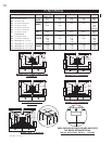
The EPI 1101 insert must be installed into a solid fuel burn-
ing fi replace that is at least 16 1/2 to 21 inches deep, 28 1/2
inches wide and 21 1/2 inches high with an approved lined
chimney at least 15 feet high (4.6m).
Your EPI
1402 fi replace insert must be installed only into a
solid fuel burning fi replace that is at least 14 inches deep 26
inches wide and 22 inches high with an approved lined chim-
ney at least 15 feet high (4.6m). This minimum recess can
only be achieved if the opening height is suffi cient enough to
allow the connector to fi t under the noncombustible facing.
The fi replace and chimney must be constructed in accordance
with all national and local building code standards.
HINT FOR INSTALLING PORCELAIN
ENAMEL INSERTS:
Ensure the base of the porcelain side panels
are protected from rubbing against the hearth
when sliding your insert into the masonry
fi replace.
Do NOT remove bricks or mortar from the fi replace. In case of
an outside air inlet or ash dump, fi ll with fi berglass insulation.
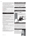
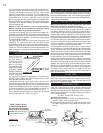
Adhere to minimum clearances as shown in FIGURE 12.
Do NOT place any com-
bustible materials (furni-
ture, fi rewood, etc.) within
48 inches in front or 36
inches at the side of the
insert.
Combustible material must
not protrude more that 1” to
the side of the insert or between the mantle and the
top of the insert.
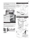
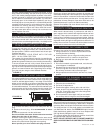
1. Remove the fi replace damper or fasten it permanently
open.
* We recommend the following method of sealing off the
damper area around the liner.
2. *Measure the throat of the fi replace and mark this shape
on a piece of 24 gauge sheet metal (fl ue cover); cut a six-inch
(6.75”) hole to lie directly below the fi replace fl ue opening.
Allow two inches of material for a fl ange on all sides and cut
to these measurements. Bend down the fl anges. If you have
never done this before, it might be a good idea to make a
cardboard pattern and test it fi rst. Fasten this fl ue cover in
position as high as possible with two masonry screws per side
through the fl anges into the fi replace. FIGURE 13.
In Canada: Install a listed 6 inch diameter fl exible stain-
less steel liner from the top of the chimney to the insert fl ue
collar. Attach a stainless steel liner connector or elbow to the
liner and insert onto the fl ue collar. Fasten with three screws.
Secure the top of the liner to the chimney cap using a liner
support and chimney fl ashing. Cap the top of the chimney
liner assembly using an approved rain cap.
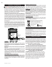
FIREPLACE INSERT
OUTSIDE AIR
PRIOR TO INSTALLATION
INSTALLATION INTO A MASONRY
FIREPLACE
FIGURE 11
Clean all ashes out of the inside of the fi replace. Make
sure that the chimney and fi replace are free of cracks,
loose mortar, creosote deposits, blockage or other signs of
deterioration. If necessary, have any repair work done by a
qualifi ed professional before installing the insert.
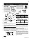
FIGURE 13
MODEL 1402 Illustrated
DAMPER
REMOVED OR
FASTENED
OPEN
FLUE
CONNECTOR
LISTED
CHIMNEY
LINER
2”
FLANGE
FLUE COVER
INSTALLATION
FIGURE 12
28" TO MANTLE
17"*
SIDE FACINGS
COMBUSTIBLE
PROTRUDING
1"*