


5
W415-0512 / D / 07.16.08
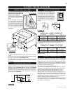
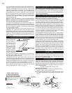
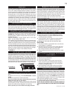
If the stove is to be installed on a
combustible fl oor, it must be placed
on an approved non-combustible
hearth pad, that extends 8” (200mm)
beyond the stove sides and back, and
18” (455mm) to the front. It must be
installed with a minimum height of
7’ between the stove base and the
ceiling.
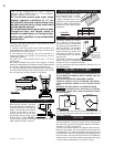
SINGLE WALL CHIMNEY CONNECTOR*
DOUBLE WALL CHIMNEY CONNECTOR
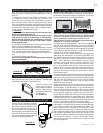
A 6” diameter single wall stove pipe, used to connect the
stove to the chimney, must be installed with the crimped end
toward the stove. This will ensure that the moisture which
condenses from the burning wood will fl ow back into the fi re
chamber. Each joint in the stove pipe must be secured with
at least three sheet metal screws.
This room heater must be connected to:
1) A chimney complying with the requirements for Type HT
chimneys in the Standard for Chimneys, Factory-Built, Resi-
dential Type and Building Heating Appliance UL 103, or
2) A code-approved masonry chimney with a fl ue liner.
Vent the stove into a masonry chimney or an approved, in-
sulated solid-fuel stainless-steel chimney with as short and
straight a length of six-inch (150mm) diameter smoke pipe
as possible. Connection to a masonry chimney must be by a
metal or masonry thimble cemented in place.
An insulated stainless steel chimney must be supported at
the ceiling or roof and its installation must comply with its
manufacturer’s instructions.
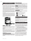
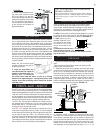
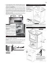
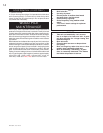
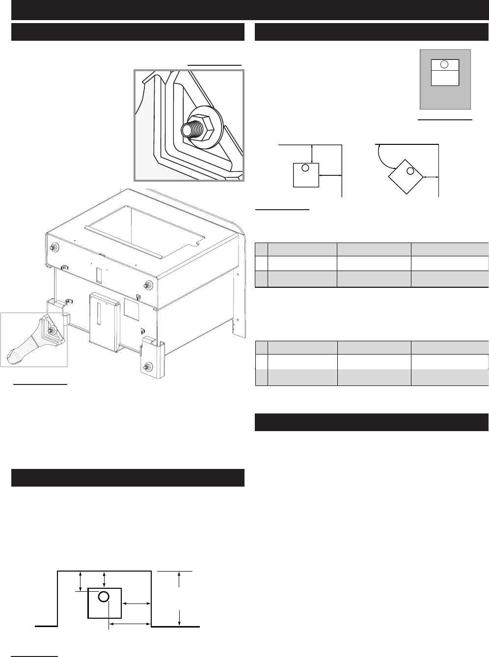
To avoid being damaged during shipping, the stove has
been bolted to the pallet and
must be unbolted before the
stove can be installed.
1. Remove the 4 nuts and wash-
ers from the underside of the
pallet.
2. Lift the stove up and away
from the pallet to clear the
threaded studs sticking through
the pallet. Place the stove on its
back onto a protective surface
such as a carpet or blanket
to avoid scratches during leg
installation.
3. Remove the four additional nuts from each of the four
studs.
4. Use four of the nuts and washers removed above to install
the legs as illustrated in FIGURES 2a & 2b.
5. Lift the stove up and gently set down on all four legs. Do
not pivot unit up on its legs, as this could result in damage
to the legs.
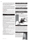
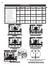
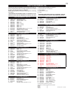
Model 1100 only may be installed, using a listed double wall
connector, such as Security DL6 in Canada, the Simpson
Duravent Plus DVL in the USA or an equivalent double wall
connector, into an alcove having a depth of no more than 4
feet and a height of at least 7 feet. The minimum clearances
are as shown in FIGURE 3.
FIGURE 2B
FIGURE 3
9"
6"
14"
23"
ALCOVE
4 FOOT
MAX
* CLEARANCES CAN BE REDUCED WITH SHIELDING ACCEPTABLE TO LOCAL
AUTHORITIES. REDUCED INSTALLATION MUST COMPY WITH NFPA 211 or
CAN/CSA-B365.
STOVE INSTALLATION
INSTALLING THE LEGS
STOVE INSTALLATION
CHIMNEY CONNECTION
ALCOVE INSTALLATION
FIGURE 2A
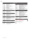
FIGURE 4A
BACK WALL
SIDE WALL
B
A
NOTE:CLEARANCES ARE UNABLE TO BE REDUCED FOR THE 1150 BY USING
DOUBLE WALL PIPE.
FIGURE 4B
A 12” (305 mm) 12” (305 mm) 22” (560 mm)
B 10” (254 mm) 12” (305 mm) 12” (305 mm)
C 6” (152 mm) 6” (152 mm) 8” (205 mm)
1100/1100L/1150 1400/1400L 1900
A 10” (254 mm) 10” (254 mm) 22” (560 mm)
B 6” (152 mm) 6” (152 mm) 12” (305 mm)
C 2” (50 mm) 4” (102 mm) 8” (205 mm)
1100/1100L 1400/1400L 1900
C
BACK WALL
45°
SIDE WALL
8"
8"
18"
8"