


6
W415-0512 / D / 07.16.08
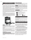
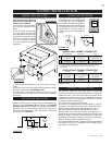
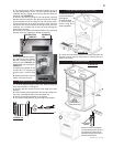
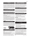
PEDESTAL BASE
4.5"
PEDESTAL BASE
FLOOR AREA BELOW STOVE
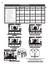
B"
A (in.) B(in.)
1100 8 5/8" 9 3/4"
1400 11 1/8" 9 3/4"
1900 14 7/8" 9 3/4"
If possible connect the air intake
at the pedestal’s back or bottom
to the outside with a 4 inch
(100mm) diameter fresh air kit
available at your Napoleon/Wolf
Steel Ltd. dealer. Follow detailed
instructions under “Mobile Home
Outside Air”.
If possible, design the installa-
tion so that the connector does
not pass through a combustible
wall. If during your installation you
must pass through a combustible
wall, check with your building
inspector before you begin. Also
check with the chimney connec-
tor manufacturer for any specifi c
requirements.
Consult with your dealer regarding
special connection components
available for use for wall pass-throughs.
Use only parts that have been tested and listed for use in a
wall pass-through.
PEDESTAL MODEL 1100 IS APPROVED FOR INSTALLA-
TION IN MOBILE HOMES IN BOTH CANADA AND THE
UNITED STATES.
1150 IS NOT APPROVED FOR MOBILE HOMES.
PEDESTAL MODEL 1400 IS APPROVED FOR INSTAL-
LATION IN MOBILE HOMES IN THE UNITED STATES
ONLY.
WARNING: DO NOT INSTALL IN SLEEPING ROOM.
CAUTION: THE STRUCTURAL INTEGRITY OF THE MO-
BILE HOME FLOOR, WALL AND CEILING/ROOF MUST
BE MAINTAINED.
The pedestal base must be fi rmly bolted to the fl oor with 1/4
inch lag bolts. Minimum clearances to combustibles are as
shown in FIGURE 9.
Connect the stove to a chimney system using a listed double
wall connector. Use a chimney system listed to ULC S629 in
Canada or UL103HT in the U.S.A.
The chimney must be installed in accordance with the manu-
facturer’s instructions. Use only specifi ed components with
no substitutions. The chimney and pipe must extend at least
8 feet above the stove and 3 feet above the highest point of
the roof. Install a rain cap at the top which will not impede the
smoke exhaust. The chimney must be supported at the ceiling
or roof so that its weight does not rest on the stove.
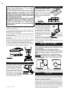
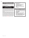
HEADERS
FIRESTOP SPACER -
UNDERSIDE OF JOIST
A
A
DO NOT USE ANY MAKESHIFT MATERIALS DUR-
ING INSTALLATION.
1. Move the stove into position with the fl ue centered, mid-
point between two joists to prevent having to cut them. Use
a plumb bob to line up the centre.
2. Cut and frame an opening in the roof to provide a 2”
clearance between the outside of the chimney and any
combustible material.
DO NOT FILL THIS SPACE WITH ANY TYPE OF
MATERIAL.
Nail headers between the joist for extra support. Firestop
spacers must be placed on the bottom of each framed opening
in any fl oor or ceiling that the chimney passes through.
3. Hold a plumb bob from the underside of the roof to deter-
mine where the opening in the roof should be. Cut and frame
the roof opening to maintain proper 2” clearances.
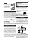
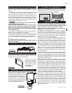
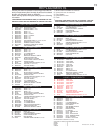
Add chimney sections, according
to the manufacturers installation in-
structions, securely, to the required
height. The chimney must extend,
at least, 3 feet above its point of
contact with the roof and at least
2 feet higher than any wall, roof or
building within 10 feet. FIGURE 6.
If your chimney system is enclosed within the attic area, a
rafter radiation shield is required.
FIGURE 5
MOBILE HOME
VENTING
ADDING CHIMNEY SECTIONS
PEDESTAL MODELS OUTSIDE AIR
THE TOTAL HORIZONTAL VENT LENGTH
SHOULD NOT EXCEED 40% OF THE CHIMNEY
HEIGHT ABOVE THE STOVE.
All horizontal smoke pipe must slope
slightly upwards a minimum of 1/4” per
foot (6mm/0.3m) and all connections must
be tight and secured by three sheet metal
screws equally spaced.
An uninsulated smoke pipe shall not pass
through an attic, roof space, closet or
similar concealed space, or through a fl oor,
ceiling, wall or partition, or any combustible
construction.
FIGURE 6
3 FT
MIN.
10 FT
2 FT
MIN.
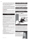
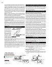
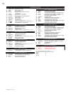
FIGURE 7
WALL PASS-THROUGH
BACK WALL
6"
SIDE WALL
10"
2"
BACK WALL
45 °
SIDE WAL
L
FIGURE 9
FIGURE 10
This is the preferred
method of passing a
flue pipe through a
combustible wall to a
masonry chimney.
FIGURE 8