


11
W415-0536 / C / 09.06.06
This application occurs
when venting through
a roof. Installation kits
for various roof pitches
are available from your
Napoleon dealer. See
Accessories to order the
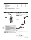
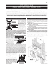
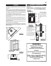
1. Determine the air
terminal location, cut
and frame 9½ or 11½
inch openings in the ceil-
ing and the roof to provide the minimum clearance between
center the exhaust pipe location midway between two joist to
prevent having to cut them. Use a plumb bob to line up the
center of the openings.
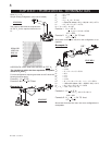
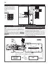
DO NOT FILL THIS SPACE WITH ANY TYPE OF MATERIAL.
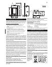
A vent pipe shield will
prevent any materi-
als such as insulation,
space around the pipe.
Nail headers between
the joist for extra sup-
port.
2. Apply a bead of
caulking (not supplied) to the framework or to the Wolf Steel
must be placed on the bottom of each framed opening in a
roof or ceiling that the venting system passes through. Apply
the vent shield to restrict cold air from being drawn into the
shield maintain the required clearance to combustibles. Once
the vent pipe / liner is installed
between the pipe / liner and the
3. In the attic, after the pipe /
liner has been installed, slide the
vent pipe collar down to cover up
the open end of the shield and
tighten. This will prevent any
materials, such as insulation,
around the pipe.
INSTALLATION
WALL AND CEILING PROTECTION
vERTICAL INSTALLATION
VENT PIPE
SHIELD
VENT
PIPE
COLLAR
FIGURE 15
FIGURE 14
11
11
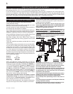
FIGURE 13
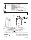
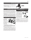
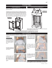
This application occurs when venting through an exterior
wall. Having determined the air terminal location, cut and
frame a hole in an exterior wall with a minimum rectangle
opening of 12” x 11”.
1. Assemble the shield to the spacer as shown, using the
3 shorter screws supplied.
The shield is meant to protect combustible materials within
the wall. If the shield is deeper than the combustible portion
spacer over the framework to restrict cold air from being drawn
into the room or around the stove. Ensure that both spacer
and shield maintain the required clearance to combustibles.
Secure the spacer in place using the 4 longer screws sup-
HORIzONTAL INSTALLATION
HORIZONTAL TERMINATION: