


5
W415-0210 / E / 06.25.03
Use only Wolf Steel or Simpson Dura-Vent Model DV-GS
venting components. Minimum and maximum vent lengths,
for both horizontal and vertical installations, and air termi-
nal locations for either system are set out in this manual
and must be adhered to. For Simpson Dura-Vent, follow
the installation procedure provided with the venting com-
ponents.
When using Wolf Steel venting components, use only ap-
proved Wolf Steel rigid / flexible components with the fol-
lowing termination kits: WALL TERMINAL KIT GD222, or
1/12 TO 7/12 PITCH ROOF TERMINAL KIT GD110, 8/12 TO
12/12 ROOF TERMINAL KIT GD111, FLAT ROOF TERMI-
NAL KIT GD112 or PERISCOPE KIT GD201 (for wall pen-
etration below grade). With flexible venting, in conjunction
with the various terminations, use either the 5 foot vent kit
GD220 or the 10 foot vent kit GD330.
Wolf Steel rigid and flexible venting systems must not
be combined.
Wolf Steel and Simpson Dura-Vent venting systems
must not be combined.
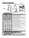
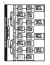
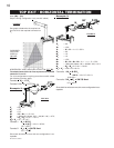
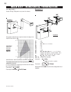
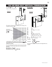
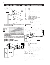
These vent kits allow for either horizontal or vertical venting
of the fireplace. FIGURES 3 & 5. The maximum allowable
horizontal run is 20 feet. The maximum allowable vertical
vent length is 40 feet. The maximum number of 4" vent
connections is two horizontally or three vertically (exclud-
ing the fireplace and the air terminal connections) when
using aluminum flexible venting.
For optimum flame appearance and fireplace perform-
ance, keep the vent length and number of elbows to a
minimum.
The air terminal must remain unobstructed at all times.
Examine the air terminal at least once a year to verify
that it is unobstructed and undamaged.
Purge all gas lines with the glass door of the fireplace
open. Assure that a continuous gas flow is at the burner
before closing the door.
Under extreme vent configurations, allow several minutes
(5-15) for the flame to stabilize after ignition.
Six (6") inches is the minimum bend radius allowed for
the 7" diameter flexible liner.
For optimum performance it is recommended that all
horizontal runs have a 1 inch rise per foot when using
Napoleon flexible vent components.
A terminal shall not terminate directly above a sidewalk
or paved driveway which is located between two sin-
gle family dwellings and serves both dwellings. Local
codes or regulations may require different clearances.
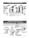
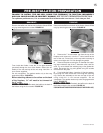
Do not allow the inside liner to bunch up on horizontal or
vertical runs and elbows. Keep it pulled tight. A 1¼" air
gap all around between the inner liner and outer liner is
required for safe operation. Use a firestop when pen-
etrating interior walls, floor or ceiling.
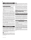
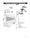
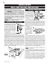
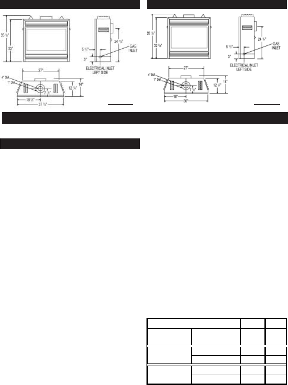
Minimum clearance to combustible con-
struction from fireplace and vent surfaces:
sides, back, bottom and top of the unit 0 inch
recessed depth 14 inches
top, sides and bottom of the vent pipe* 1 inch
top of the vent pipe - rear vent only* 2 inches
* REAR VENT - A clearance to combustibles of 1" at the
bottom of the vent and 2" at the top must be maintained
during the first 12" of venting when penetrating combusti-
ble walls. The firestop spacer (W615-044) supplied with
the unit should be used to maintain this clearance. There-
after a 1" clearance to combustibles may be maintained
using firestop spacer (W500-0096).
TOP VENT - Only a clearance to combustibles of 1" all
around the vent pipe is required.
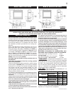
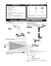
MODELS GD36 AND BGD36 MAY BE VENTED EITHER AS A TOP VENT OR A REAR VENT.
REFER TO THE SECTION APPLICABLE TO YOUR INSTALLATION.
RIGID VENTING 0"/FT 1"/FT*
FLEXIBLE VENTING 0"/FT 1"/FT*
RIGID VENTING 0"/FT 0"/FT
FLEXIBLE VENTING 0"/FT 0"/FT
RIGID VENTING 0" 6"
FLEXIBLE VENTING 6" 6"
REAR VENT
TOP VENT
CORNER
REQUIRED RISE ON HORIZONTAL VENTING
BGD36 GD36
* When a vertical rise is used as part of the venting con-
figuration, a 0" rise per foot is acceptable.
VENTING LENGTHS
GD36 SPECIFICATIONS
VENTING
BGD36 SPECIFICATIONS
FIGURE 1a FIGURE 1b