


14
W415-0210 / E / 06.25.03
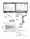
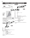
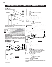
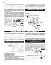
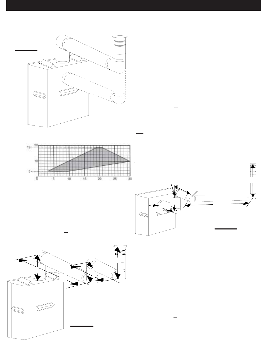
MAXIMUM
VERTICAL
RISE IN
FEET
V
T
HORIZONTAL VENT RUN PLUS OFFSET IN FEET
H
T
The shaded area within the lines represents acceptable
values for H
T
and V
T
.
For vent configurations requiring more than two 90° elbow
(top exit) or one 90° elbow (rear exit), the following formu-
las apply:
Formula 1: H
T
< 3V
T
Formula 2: H
T
+ V
T
< 40 feet
Example 7:
See graph to determine the required vertical rise V
T
for the
required horizontal run H
T
.
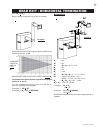
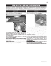
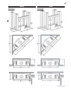
FIGURE 18
V
1
=2 ft
V
2
=1 ft
V
3
=1.5 ft
V
T
=
V
1
+
V
2
+
V
3
=
2 + 1 + 1.5 = 4.5 ft
H
1
=6 ft
H
2
=2 ft
H
R
=H
1
+ H
2
= 6 + 2 = 8 ft
H
O
=.03(four 90° elbows - 90°)
=.03(90 + 90 + 90 + 90 - 90) = 8.1 ft
H
T
=H
R
+ H
O
= 8 + 8.1 = 16.1 ft
H
T
+ V
T
= 16.1 + 4.5 = 20.6 ft
Formula 1: H
T
< 3V
T
3V
T
=
3 x
4.5 = 13.5 ft
16.1 > 13.5
Since this formula is not met, this vent configuration is
unacceptable.
Formula 2: H
T
+ V
T
< 40 feet
20.6 < 40
Since only formula 2 is met, this vent configuration is unac-
ceptable and a new fireplace location or vent configuration
will need to be established to satisfy both formulas.
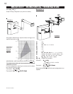
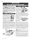
Example 8:
V
1
=1.5 ft
V
2
=5 ft
V
T
=
V
1
+
V
2
=
1.5 + 5 = 6.5 ft
H
1
=1 ft
H
2
=1 ft
H
3
=10.75 ft
H
R
=H
1
+ H
2
+ H
3
= 1 + 1 + 10.75 = 12.75 ft
H
O
=.03(three 90° elbows + one 45° elbow - 90°)
=.03(90 + 90 + 90 + 45 - 90) = 6.75 ft
H
T
=H
R
+ H
O
= 12.75 + 6.75 = 19.5 ft
H
T
+ V
T
= 19.5 + 6.5 = 26 ft
Formula 1: H
T
< 3V
T
3V
T
=
3 x
6.5 = 19.5 ft
19.5 = 19.5
Formula 2: H
T
+ V
T
< 40 feet
26 < 40
Since both formulas are met, this vent configuration is ac-
ceptable.
FIGURE 19
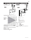
FIGURE 17
H
1
H
2
V
3
V
1
90°
90°
90°
V
2
90°
H
2
H
3
V
1
V
2
90°
45°
90°
H
1
90°
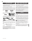
when (H
T
) > (V
T
)
Simple venting configurations
TOP OR REAR EXIT VERTICAL TERMINATION