


19
W415-0210 / E / 06.25.03
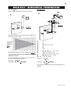
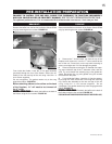
Before attaching elbows to the collars on the back
of the fireplace, 1½" will need to be trimmed off
the 4" collar.
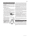
REAR VENT APPLICATION: Attach 4" and 7" elbows to
the fireplace. Secure with 3 screws and seal the joints and
screw heads using high temperature sealant. Proceed to
step 1 below.
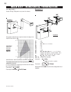
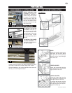
TOP VENT APPLICATION:
1. Move the fireplace into position.
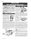
2. Fasten the roof support to the roof using the screws
provided. FIGURE 30. The roof support is optional. In this
case the venting is to be adequately supported using ei-
ther an alternate method suitable to the authority having
jurisdiction or the optional roof support.
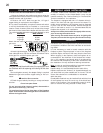
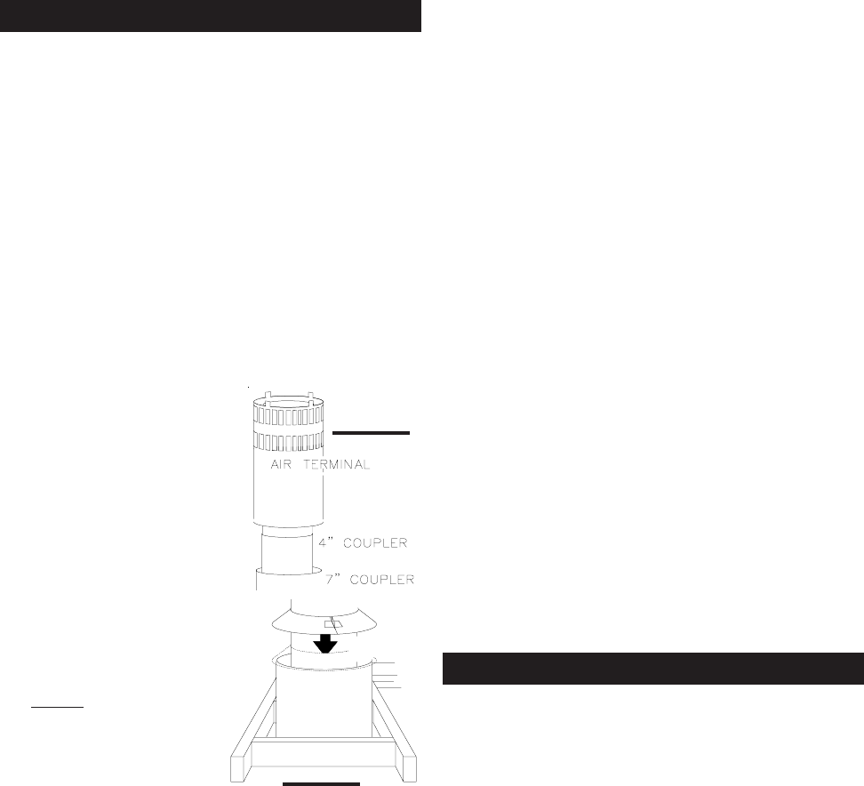
3. Apply high temperature sealant to the outer edge of the
inner sleeve of the air terminal. Slip a 4" diameter coupler a
minimum of 2" over the sleeve and secure using 3 screws.
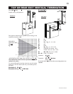
4. Apply high temperature seal-
ant to the outer edge of the of the
outside sleeve of the air terminal.
Slip a 7" diameter coupler over the
sleeve and secure as before. Trim
the 7" coupler even with the 4" cou-
pler end.
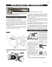
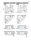
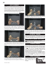
5. Thread the air terminal pipe
assembly down through the roof
support and attach, ensuring that
a minimum 16" of air terminal will
penetrate the roof when fastened.
If the attic space is tight, we rec-
ommend threading the Wolf
Steel vent pipe collar or equiva-
lent
loosely onto the air terminal
assembly as it is passed through
the attic. The air terminal must be
located vertically and plumb.
VENT PIPE
SHIELD
VEN
T
PIP
E
COLLA
R
FIGURE 36
FIGURE 35
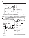
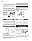
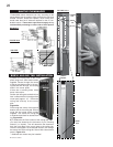
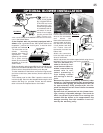
6. Remove nails from the shingles, above and to the
sides of the chimney. Place the flashing over the air termi-
nal and slide it underneath the sides and upper edge of
the shingles. Ensure that the air terminal is properly
centered within the flashing, giving a 3/4" margin all around.
Fasten to the roof. Do NOT nail through the lower portion of
the flashing. Make weather-tight by sealing with caulking.
Where possible, cover the sides and top edges of the flash-
ing with roofing material.
7. Apply a heavy bead of waterproof caulking 2 inches
above the flashing. Slide the storm collar around the air
terminal and down to the caulking. Tighten to ensure that a
weather-tight seal between the air terminal and the collar
is achieved. Attach the other storm collar centered between
the air intake and air exhaust slots onto the air terminal.
Tighten securely. Attach the rain cap.
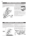
8. Continue adding rigid venting sections, sealing and
securing as above. Attach a 4" collapsed telescopic pipe
to the last section of rigid piping. Secure with screws and
seal. Repeat using a 7" telescopic pipe.
9. REAR VENT APPLICATION: Run a bead of high tem-
perature sealant around the outside of the 4" elbow. Pull
the adjustable pipe a minimum 2" onto the elbow. Secure
with 3 screws. Repeat with the 7" telescopic pipe.
TOP VENT APPLICATION: Run a bead of high tempera-
ture sealant around the outside of the 4" collar on the fire-
place. Pull the adjustable pipe a minimum of 2" onto the
collar. Secure with 3 screws. Repeat with the 7" telescopic
pipe.
10. In the attic, slide the vent pipe collar down to cover up
the open end of the shield and tighten. This will prevent
any materials, such as insulation, from filling up the 1" air
space around the pipe.
Model GD36NTR Vertical Terminal only:
Vertical terminations running longer than 15 feet may dis-
play a very active flame. If this appearance is not desirable,
the vent exit must be restricted using restrictor plate kit,
RP-KT. This reduces the velocity of the exhaust gases,
slowing down the flame pattern and creating a more tradi-
tional appearance. Specific instructions are included with
the kit.
RESTRICTING VERTICAL VENTS
VERTICAL VENTING INSTALLATION