


15
W415-0210 / E / 06.25.03
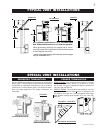
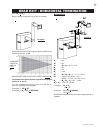
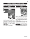
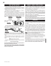
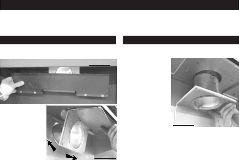
Remove the baffle from the back of the firebox (Model GD36
only) by removing the four screws. FIGURE 20.
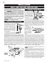
From inside the firebox, insert the 4" flue pipe assembly
(provided) through the rear of the firebox. Secure the as-
sembly to the rear and top of the unit using 4 #10-24 x ½
inch screws supplied.
Do not overtighten. The gasket needs only to be snug
against the firebox. FIGURE 21.
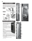
Before attaching elbows to the collars on the back
of the fireplace, 1½" will need to be trimmed off
the 4" collar.
MODEL GD36 ONLMODEL GD36 ONL
MODEL GD36 ONLMODEL GD36 ONL
MODEL GD36 ONL
YY
YY
Y
::
::
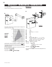
: Re-attach the baffle to the back of
the firebox using the four screws. FIGURE 20.
Remove the baffle from the back of the firebox (Model GD36
only) by removing the four screws. FIGURE 20.
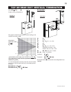
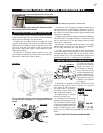
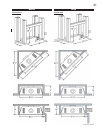
1. Remove the 7 inch diameter cap from the top of the
fireplace and re-secure it over the 7" collar located at the
rear of the unit. Press firmly on the cap while securing to
ensure an airtight seal. Do not damage the gasket.
2. Remove the plate covering the 4" diameter flue open-
ing (seen inside the top of the 7" diameter collar) and dis-
card. Try not to disturb the retaining ring or the gasket be-
neath. Re-secure the ring and gasket using the screws
removed from the plate.
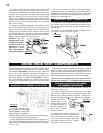
3. From inside the firebox, insert the 4" flue pipe assem-
bly through the heat shield and out through the retaining
ring. Secure the assembly to the rear and top of the unit
using 4 #10-24 x ½ inch screws supplied. Do not
overtighten. The gasket needs only to be snug against the
firebox. FIGURE 22.
MODEL GD36 ONLMODEL GD36 ONL
MODEL GD36 ONLMODEL GD36 ONL
MODEL GD36 ONL
YY
YY
Y
::
::
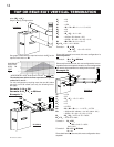
: Re-attach the baffle to the back of
the firebox using the four screws. FIGURE 20.
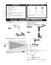
FOR SAFE AND PROPER OPERATION OF THE FIREPLACE,
FIGURE 22
FAILURE TO INSTALL THE CAP WILL CAUSE THE FIREPLACE TO FUNCTION IMPROPERLY
AND CAN CAUSE INJURY OR PROPERTY DAMAGE.
SEE TOP EXIT PREPARATION FOR DETAILS.
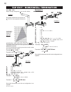
For optimum performance, it is recommended that all horizontal runs have a 1 inch rise per foot.
BAFFLE SCREWS
FIGURE 21
FIGURE 20
BAFFLE
PRE-INSTALLATION PREPARATION
REAR EXIT: TOP EXIT: