


18
VENTING
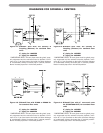
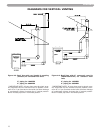
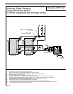
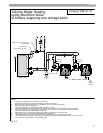
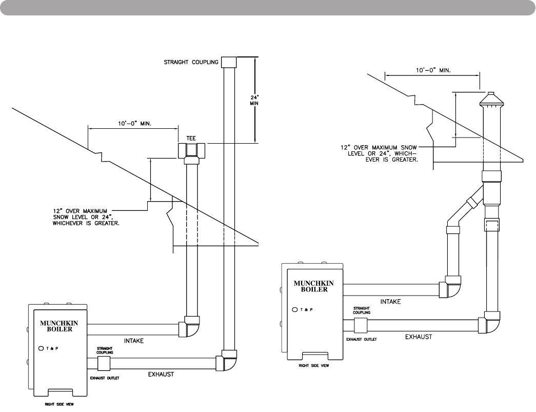
DIAGRAMS FOR VERTICAL VENTING
Figure 4-5: Roof Vent with tee (intake) & coupling
(exhaust) for standard floor units
3” piping for 199VWH
4” piping for 399VWH
**IMPORTANT NOTE: All vent pipes must be glued, prop-
erly supported and the exhaust must be pitched a mini-
mum of a ¼" per foot back to the boiler (to allow drainage
of condensate). Always increase pipe in vertical position.
Never increase pipe size in horizontal position.
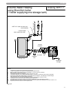
Figure 4-6: Roof Vent with 3” concentric vent kit
(KGAVT0601CVT) for standard floor
units
3” piping for 199VWH
4” piping for 399VWH
**IMPORTANT NOTE: All vent pipes must be glued, prop-
erly supported and the exhaust must be pitched a mini-
mum of a ¼" per foot back to the boiler (to allow drainage
of condensate). Always increase pipe in vertical position.
Never increase pipe size in horizontal position.