


10
GAS CONNECTION
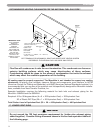
PART 3. GAS CONNECTION
A. GAS CONNECTION
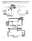
The gas supply shall have a maximum inlet pressure of less than 14” water column (350 mm), ½ pound
pressure (3.5 kPa), and a minimum of 7” water column. The entire piping system, gas meter and
regulator must be sized properly to prevent pressure drop greater than 0.5” as stated in the National
Fuel Gas Code. This information is listed on the rating plate. It is very important that you are
connected to the type of gas as noted on the rating plate. “LP” for liquefied petroleum, propane gas
or, “Nat” natural or city gas. All gas connections must be approved by the local gas supplier, or utility
in addition to the governing authority, prior to turning the gas supply on. The nipple provided for the
399VWH is 1
1
/
4” with a mandatory 1 x 1
1
/
4 reducing coupling (provided). Threaded into the branch of
a 1
1
/4” tee and a drip leg fabricated as per the national fuel gas code. The 199VWH has a
3
/4” gas supply
nipple with a
1
/2 x
3
/4 reducing coupling (provided) which is to be threaded into the branch of a
3
/4” tee.
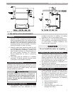
You must ensure that the entire gas line to the connection at the Munchkin is no smaller than 1
1
/
4”
for the 399VWH and
3
/
4” for the 199VWH. Once all the inspections have been performed, the piping
must be leak tested. If the leak test requirement is a higher test pressure than the maximum inlet
pressure, you must isolate the Munchkin from the gas line. In order to do this, you must shut the gas
off using factory and field-installed gas cocks (following the lighting instructions in Part 6 Section B.)
This will prevent high pressure. Failure to do so may damage the gas valve. In the event the gas valve
is exposed to a pressure greater than
1
/2 PSI, 14” water column, the gas valve must be replaced. Never
use an open flame (match, lighter, etc.) to check gas connections.
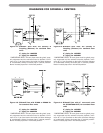
B. GAS PIPING
1. Run the gas supply line in accordance with all applicable codes.
2. Locate and install manual shutoff valves in accordance with state and local requirements.
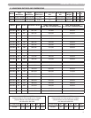
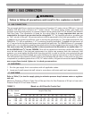
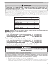
C. GAS TABLE
Refer to Table (1) to size the supply piping to minimize pressure drop between meter or regulator
and unit.
Maximum Capacity of Pipe in Cubic Feet of Gas per Hour for Gas Pressures of 0.5 psi or Less and a
Pressure Drop of 0.3 Inch water Column
(TABLE 1) (Based on a 0.60 Specific Gravity Gas)
WARNING
Failure to follow all precautions could result in fire, explosion or death!
Nominal
Iron Pipe Internal Length of Pipe (Feet)
Size Diameter
(inches) (inches) 10 20 30 40 50 60 70 80 90 100 125 150 175 200.
3/4 .824 278 190 152 130 115 105 96 90 84 79 72 64 59 55} BTU'S
1 1.049 520 350 285 245 215 195 180 170 160 150 130 120 110 100} PER
1 1/4 1.380 1,050 730 590 500 440 400 370 350 320 305 275 250 225 210} HOUR
1 1/2 1.610 1,600 1,100 890 760 670 610 560 530 490 460 410 380 350 320} X 1,000