


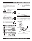
MAYCO ST-45HRM PUMP — OPERATION & PARTS MANUAL — REV. #4 (07/16/04) — PAGE 47
ST-45 PUMP — MAINTENANCE (PUMP)
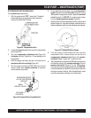
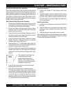
ST45 PRESSURE SETTING SEQUENCE
To set
maximum
pump pressure:
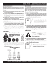
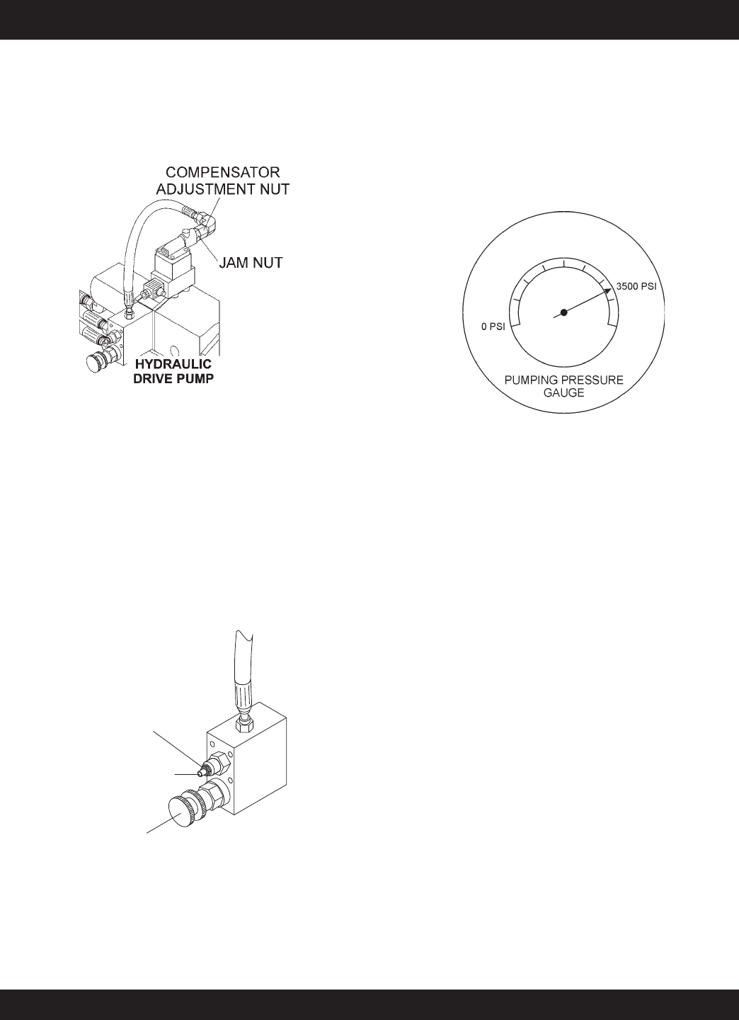
1. With the engine turned “OFF”, loosen the ¼” hydraulic
hose attached to the compensator valve located on
the top of the Main Delta Q Pump.
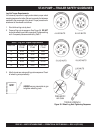
2. Loosen the
jam nut
located on the end of the compensator
valve (Figure 44).
3. Turn the
compensator adjustment nut
(Figure 44)
clockwise
until tight. Tighten the ¼” hose leading to the
compensator.
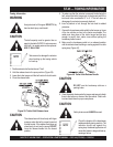
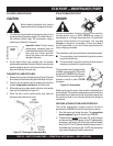
4. Start the engine and loosen the jam nut located on the
maximum relief valve cartridge
(Figure 45).
5. Run the engine at maximum RPM (2550) and turn the
volume control knob
counter-clockwise
to maximum
volume position (Figure 45).
Figure 44. Compensator Valve
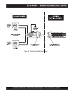
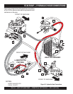
MAXIMUM RELIEF
VALVE CARTRIDGE
JAM NUT
MAIN
RELIEF VALVE
VOLUME
CONTROL
Figure 45. Hydraulic Drive Pump Manifold
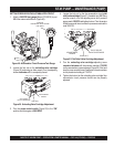
6. On the electrical control panel, turn the
pump control
switch
(Figure 22) and the
test switch
(Figure 31) to the
“ON” position. Using an allen wrench, adjust the
main relief
valve
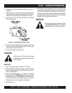
(Figure 45) to 3500 PSI. The reading can be taken
from the
pumping pressure gauge
(Figure 46).
7. Hold the main relief valve adjusting bolt with a wrench and
tighten the jam nut. Using the test switch, double check the
pressure reading to make sure the setting has not changed.
Figure 46. Pumping Pressure Gauge
8. Turn the engine off and loosen the hose from the
compensator valve. Loosen the jam nut and turn the
compensator adjustment nut
(Figure 44)
counter-
clockwise
½ turn. Tighten the ¼” hydraulic hose.
9. Start engine and run at maximum RPM with volume control
at maximum volume (fully
counter-clockwise
). Turn the
pressure test switch
(Figure 31) to the “ON” position.
The pumping pressure gauge should now read 3300 PSI.
It may be necessary to repeat the above steps to achieve
the proper pressure settings. After the adjustment, make
sure the compensator valve jam nut is locked tight.