PAGE 22 — MAYCO ST-45HRM PUMP — OPERATION & PARTS MANUAL — REV. #4 (07/16/04)
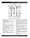
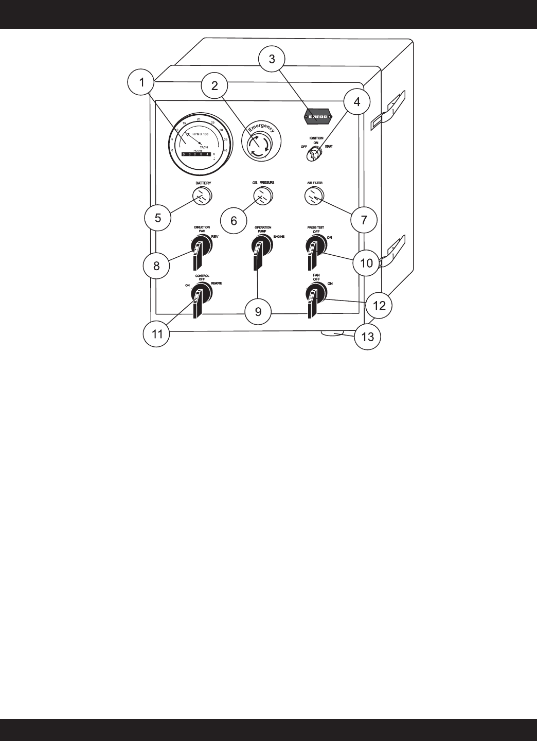
ST-45 PUMP — CONTROL BOX COMPONENTS
Figure 8. Pump Control Box Components
1. Engine Tachometer – Monitors the engine RPM’s and
hours of operation for the engine.
2. Emergency Stop Button – Press emergency stop button
to stop pump in an emergency. Turn knob counter clockwise
to disengage the stop button.
3. Hourmeter – Display's the number of hours the pump has
been in use.
4. Ignition Switch – Insert the ignition key here to start the
engine. Turn the key clockwise to the “ON“ position, then
continue turning clockwise to the “START“ position and
release. To stop the engine turn the key fully counter-
clockwise to the “STOP“ position.
5. Battery Indicator Lamp– Indicates a low battery charge.
Replace or charge battery.
NEVER operate the ST-45 when
this lamp is on.
6. Oil Pressure Indicator Lamp– When lit, indicates correct
operational pressure for running the ST-45. NEVER operate
the ST-45 if this lamp is off.
7. Air Filter Indicator Lamp – Indicates the engine air filter
is functioning properly. NEVER operate the ST-45 if this
lamp is off.
8. Direction Control Switch– This 2 position switch controls
the direction of flow for any mix in the pump. The
center
position sets the pumping direction to forward and the
right
most
position sets the pumping direction to reverse.
9. Pump Operation Switch– This 2 position switch controls
the operation of the pumping components and engine. The
center
position allows the operation of the pump and
engine and the
right most
position allows only the engine
to operate.
10. Pressure Test Switch– Activates a self-diagnostic routine
which tests the pressure of the pumping system, which can
be read on the Pumping Pressure Gauge.
11. Pumping Control Switch – This 3-position switch controls
the pumping of the pump. The
left most
position is for use
with the remote control unit, the
center
position is for
normal pumping operation, and the
right most
position
(OFF) prevents pumping.
12. Cooling Fan Switch – If hydraulic oil temperature exeeds
75° F, set the pump operation switch to engine and turn the
cooling fan switch to the right most position to activate
cooling fan.
13. Remote Cable Connector – Insert the remote control input
cable into this connector.


