


PAGE 4 — MAYCO ST-45HRM PUMP — OPERATION & PARTS MANUAL — REV. #4 (07/16/04)
TABLE OF CONTENTS
Specification and part
number are subject to
change without notice.
NOTE
MAYCO ST-45HRM
STRUCTURAL CONCRETE
PUMP
Proposition 65 Warning .............................................2
Here’s how To Get Help.............................................3
Table of Contents ......................................................4
Parts Ordering Procedures ...................................... 5
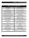
Pump Specifications..................................................6
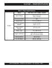
Engine Specifications ................................................7
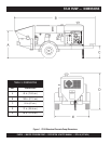
Dimensions .............................................................. 8
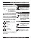
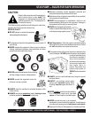
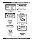
Safety Message Alert Symbols .......................... 9-10
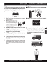
Rules for Safe Operation ................................... 11-13
Operation and Safety Decals ............................ 14-15
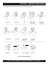
Important Hand Signals ..........................................16
General Information .......................................... 17-18
How it Works............................................................19
Pump Components ........................................... 20-21
Control Box Components ........................................22
Engine Components ...............................................23
Operating Procedures....................................... 24-28
Inspection.......................................................... 29-31
Initial Start-Up Procedure ................................. 32-35
Towing Guidelines ............................................. 36-37
Trailer Safety Guidelines ................................... 38-40
Towing Information ............................................ 41-42
Wiring Diagram (Tail Lights)....................................43
Maintenance (Pump) ........................................ 44-52
Hydraulic Hose Connections ............................. 54-56
Manifold Port Locations...........................................57
Appendix — Concrete Mix Information ............. 58-59
Appendix — Slump Test Procedure ........................60
Troubleshooting (Engine) ........................................61
Troubleshooting (Hydraulic System) .......................62
Troubleshooting (Electrical System) .......................63
Troubleshooting (Brake System).............................64
PARTS ILLUSTRATIONS
Explanation Of Code In Remarks Column ..............64
Suggested Spare Parts ...........................................65
Appendix — Recommended
Shotcrete System ............................... 66
Appendix — Recommended
Shotcrete Accessories ........................ 68
Decal Placement ................................................70-71
Axle Assembly ....................................................74-75
Brakeline Assembly ............................................76-77
Hopper Assembly ...............................................78-79
Hopper Attachment Assembly ...........................80-81
Hopper Interior Assembly ..................................82-83
Shuttle Cylinder Assembly .................................84-85
Fuel and Hydraulic Tank Assembly ....................86-89
Front Cover Assembly........................................90-91
Heat Exchanger Assembly .................................92-93
Engine and Frame Assembly .............................94-96
Throttle and Water Filter Assembly ....................96-97
Hydraulic Pump Assembly .................................98-99
Lubrication Pistons Assembly ........................100-101
Electrical System Assembly ...........................102-103
Accumulator Assembly...................................104-105
Manifold Assembly .........................................106-107
Remixer Control Assembly .............................108-109
Battery Assembly ...........................................110-111
Lubrication Panel ...........................................112-113
Taillight Assembly ...........................................114-115
Control Box Interior Door Assembly ...............116-117
Control Box Mounting Assembly ...................118-119
Control Box Assembly ...................................120-121
Control Box Door Wiring Diagram ......................... 122
Control Box Interior Wiring Diagram ..................... 123
Terminal Block Wiring Diagram ............................. 124
Control Box Electrical Schematic ...................125-126
Interconnect Hydraulic Control Box ...................... 127
Hydraulic Diagram ............................................... 128
Optional Radio Control.......................................... 129
Terms and Conditions Of Sale — Parts ................ 130
Mayco Pump Warranty .......................................... 131