


42D0200
Designer Series Gas Fireplaces
17
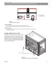
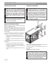
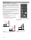
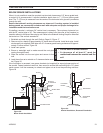
When installed as a rear vent unit this appliance may be vented directly to a termination located on
the rear wall behind the appliance
• The maximum horizontal distance between the rear of the appliance and the outside face of the
rear wall is 20" (508 m). Figure 16
• Only one 45° elbow is allowed in these installations.
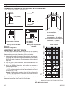
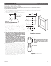
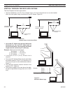
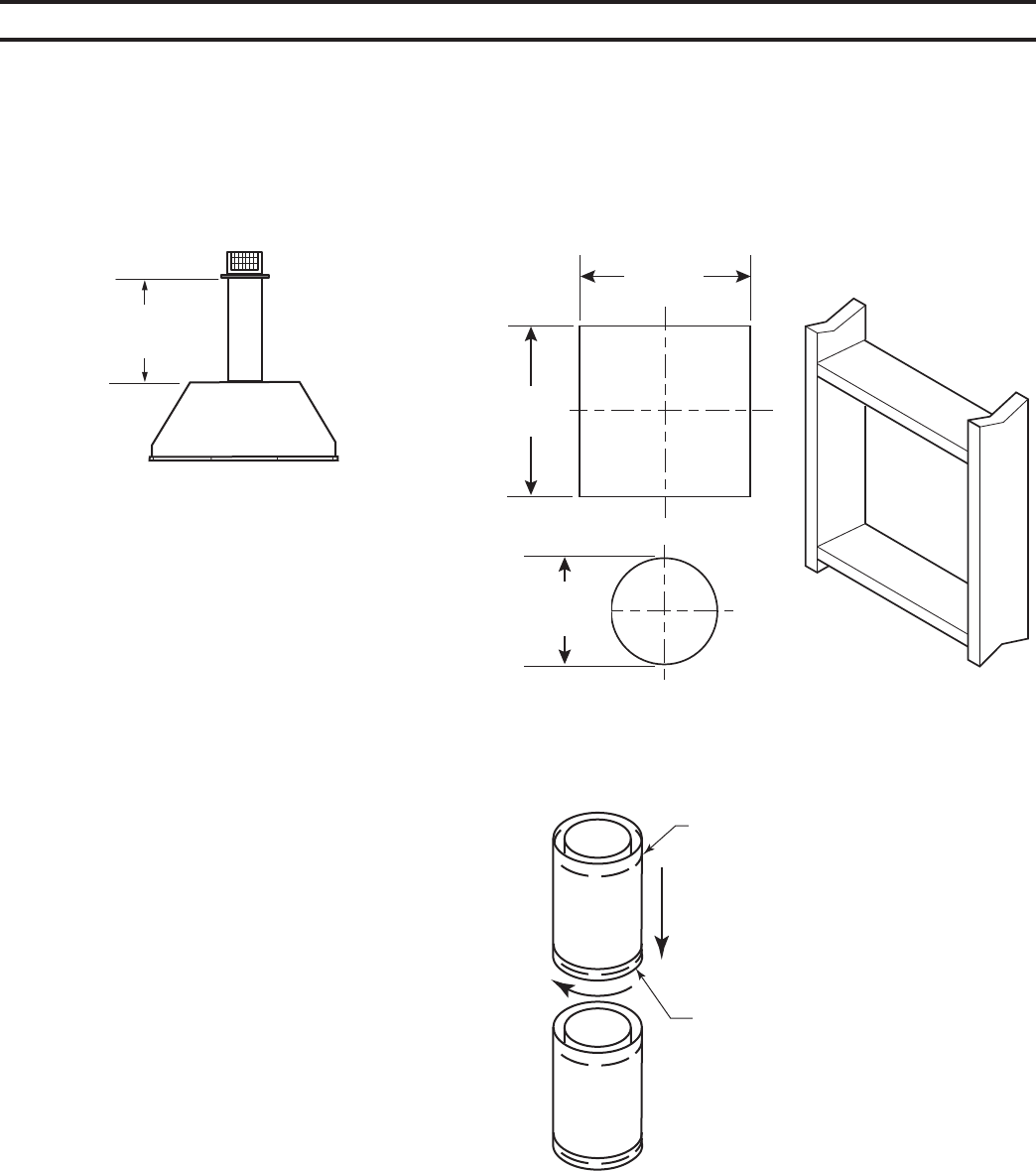
1. Locate and cut the vent opening in the wall. For
combustible walls first frame in opening.
Cut a 11Z\x"H x 9Z\x" W (292 x
241 mm) hole through the exterior wall and frame as
shown. Figure 17
Hole opening should be 7Z\x"
(190 mm) in diameter.
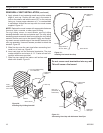
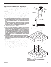
2. Rigid vent pipes and fittings have special twist-lock
connections. Assemble the desired combination of
pipe and elbows to the appliance adaptor with pipe
seams oriented towards the wall or floor.
Twist-lock Procedure: The female ends of the pipes
and fittings have three locking lugs (indentations).
These lugs will slide straight into matching slots on
the male end of adjacent pipes and fittings. Push the
pipe sections together and twist one section clockwise
approximately one-quarter turn until the sections are
fully locked. Figure 18
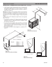
3. Attach vent pipe assembly to the fireplace. Set fire-
place in front of its permanent location to insure mini-
mum clearances. Mark the wall for a 11Z\x"H x 9Z\x"W
(292 x 241 mm) rectangle hole (for noncombustible
material such as masonry block or concrete, a 7Z\x"
[190 mm] diameter hole is acceptable). Figure 17.
The center of the hole should line up with the center
line of the horizontal rigid vent pipe end. Be sure to
allow for minimum rise. Cut a 11Z\x"x9Z\x" rectangle hole
through combustible exterior wall (7Z\x" diameter hole
if noncombustible). Frame as necessary. Allow 1/4"
minimum rise per foot. Figure 17
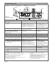
Figure 16 -
Rear Vent Application, Maximum
Horizontal Distance
Top View Flat
Installation
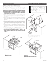
Figure 17 -
Vent Opening Requirements
FP1954
wall framing
9Z\x"
(241 mm)
11Z\x"
(292 mm)
7Z\x"
(190 mm)
FP1954
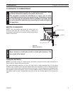
Horizontal runs of vent must
be supported every three (3) feet
(914 mm). Use wall straps for this
purpose.
Figure 18 -
Rigid Vent Pipe Connections
Female Locking
Lugs
Male Slots
FP1953
rigid pipe
FP1953
DVR584-600
Rear vent no elbows
2/99 djt
20"
(508 mm)