


6
a
d
cb
ef
90°
d
c
b
a
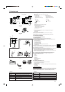
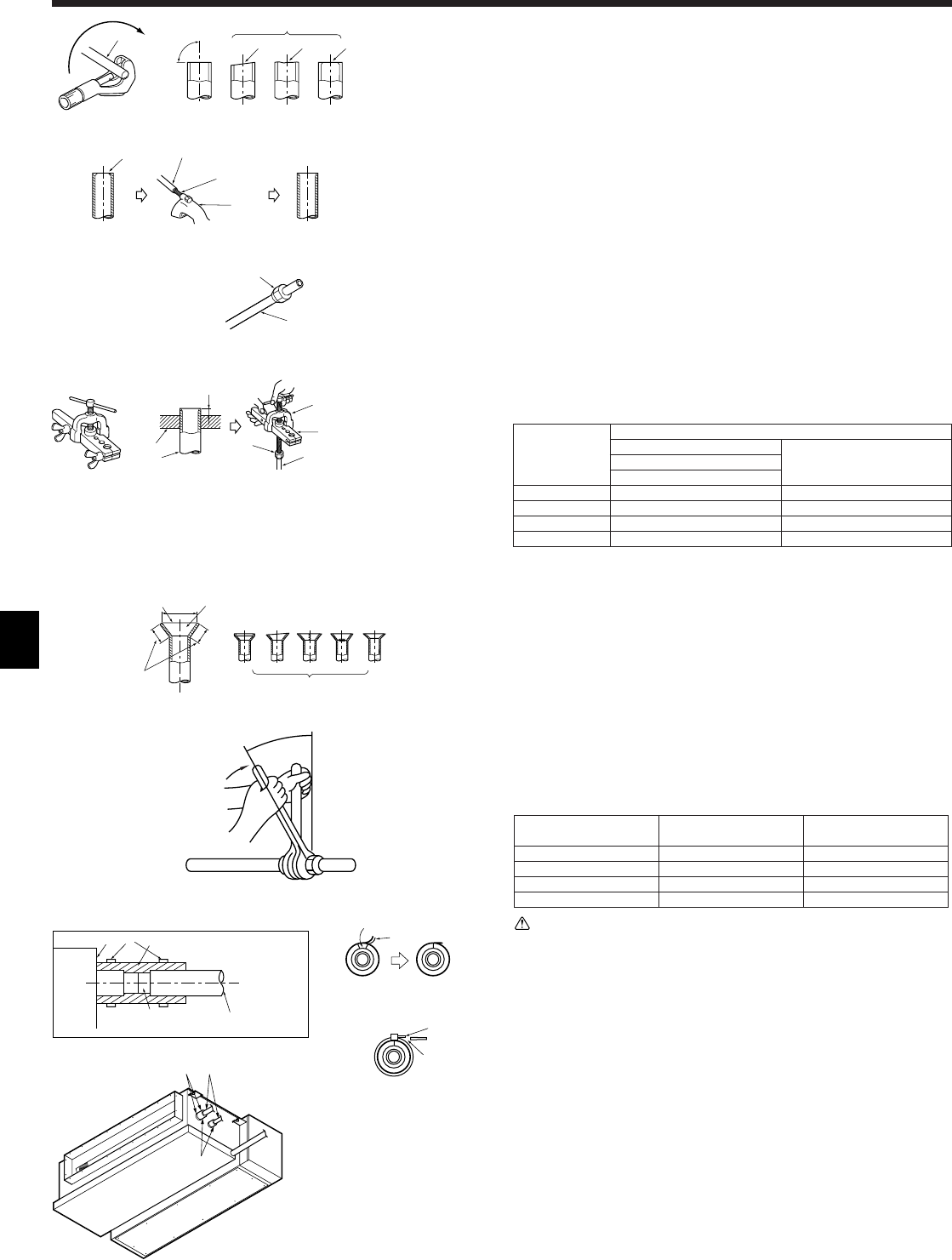
5. Refrigerant piping work
b
a
a
b
e
b
c
d
c
A
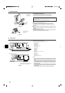
5.2. Flaring work
• Main cause of gas leakage is defect in flaring work.
Carry out correct flaring work in the following procedure.
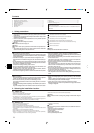
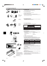
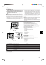
5.2.1. Pipe cutting (Fig. 5-3)
• Using a pipe cutter cut the copper tube correctly.
5.2.2. Burrs removal (Fig. 5-4)
• Completely remove all burrs from the cut cross section of pipe/tube.
• Put the end of the copper tube/pipe to downward direction as you remove burrs in
order to avoid burrs drop in the tubing.
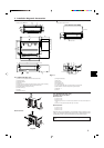
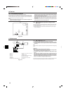
5.2.3. Putting nut on (Fig. 5-5)
• Remove flare nuts attached to indoor and outdoor unit, then put them on pipe/tube
having completed burr removal.
(not possible to put them on after flaring work)
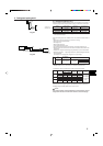
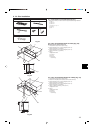
5.2.4. Flaring work (Fig. 5-6)
• Carry out flaring work using flaring tool as shown at the right.
Dimension
Pipe diameter A (mm)
(mm)
When the tool for R410A is used
B (mm)
Clutch type
6.35 0 - 0.5 9.1
9.52 0 - 0.5 13.2
12.7 0 - 0.5 16.6
15.88 0 - 0.5 19.7
Firmly hold copper tube in a die in the dimension shown in the table at above.
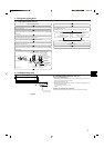
5.2.5. Check (Fig. 5-7)
• Compare the flared work with a figure in right side hand.
• If flare is noted to be defective, cut off the flared section and do flaring work again.
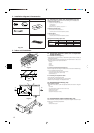
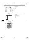
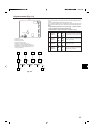
5.3. Pipe connection (Fig.5-8)
• Apply a thin coat of refrigeration oil on the seat surface of pipe.
• For connection first align the center, then tighten the first 3 to 4 turns of flare nut.
• Use tightening torque table below as a guideline for indoor unit side union joint section,
and tighten using two wrenches. Excessive tightening damages the flare section.
Copper pipe O.D. Flare nut O.D. Tightening torque
(mm) (mm) (N·m)
ø6.35 17 14 - 18
ø9.52 22 34 - 42
ø12.7 26 49 - 61
ø15.88 29 68 - 82
Warning:
Be careful of flying flare nut! (Internally pressurized)
Remove the flare nut as follows:
1. Loosen the nut until you hear a hissing noise.
2. Do not remove the nut until the gas has been completely released (i.e., hiss-
ing noise stops).
3. Check that the gas has been completely released, and then remove the nut.
Outdoor unit connection
Connect pipes to stop valve pipe joint of the outdoor unit in the same manner applied
for indoor unit.
• For tightening use a torque wrench or spanner, and use the same tightening torque
applied for indoor unit.
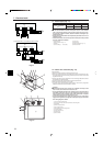
Refrigerant pipe insulation (Fig. 5-9)
(1) Peel the separator sheet off the accompanying pipe cover, and wrap it around the
refrigerant pipe, making sure that the side which is slit faces upwards.
(2) Be sure to fix both ends of the pipe cover using an attachment band (ensure that
the band’s joint faces upwards).
(3) Stick vinyl tape on the joint positions.
a Copper tubes
b Good
c No good
d Tilted
e Uneven
f Burred
Fig. 5-3
Fig. 5-4
a Burr
b Copper tube/pipe
c Spare reamer
d Pipe cutter
Fig. 5-5
Fig. 5-6
Fig. 5-7
Fig. 5-8
Fig. 5-9
a Flare nut
b Copper tube
a Flaring tool
b Die
c Copper tube
d Flare nut
e Yo k e
a
f
c
b
d
e
b
c
e
g
h
c
i
a Indoor unit (main unit)
b 1 Pipe cover
c 2 Band
d Flare joint
e Refrigerant pipe and insulating ma-
terial (must be supplied locally)
f Position the pipe cover so that the end
is in firm contact with the main unit.
Fasten it so that there is no clearance.
g Allow no clearance
h Separator sheet
i Cut off the remainder band
a Smooth all around
b Inside is shining without any scratches
c Even length all around
d Too much
e Tilted
f Scratch on flared plane
g Cracked
h Uneven
i Bad examples
c
b
a
defgh
i
B
+0
-0.4