


4
AB
1
2
3
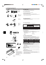
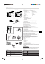
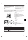
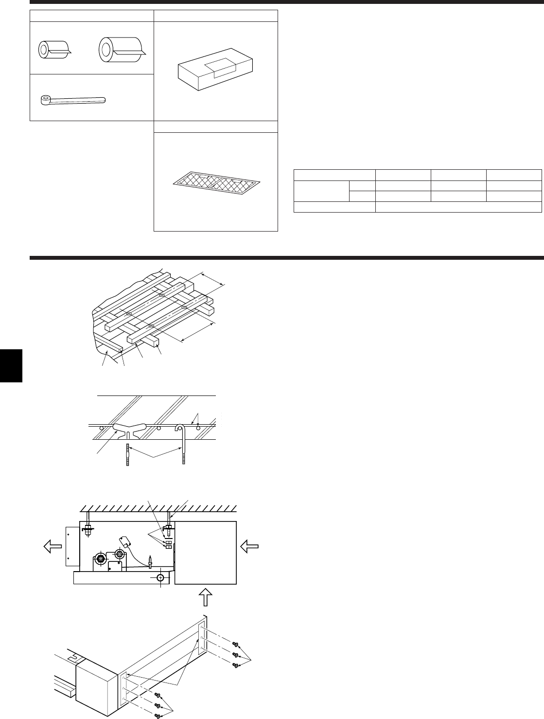
3. Installation diagram & Accessories
Fig. 3-3
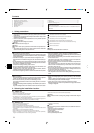
3.3. Checking the indoor unit accessories (Fig. 3-3)
Check that the indoor unit is equipped with the following parts and accessories:
A Refrigerant pipe parts
1 Pipe cover (for refrigerant piping joint)
Small diameter × 1
Large diameter × 1
2 Bands for temporary tightening of pipe cover × 4
B Remote controller parts
3 Parts contained in the cardboard box × 1
Check the contents and read the explanations provided.
C Air filter parts
4 Parts contained in the bag × 1
Check the contents and read the explanations provided.
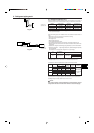
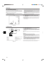
Refrigerant and drainage pipe sizes
Model SEZ-A12AR SEZ-A18AR SEZ-A24AR
Refrigerant Liquid OD ø6.35 (1/4") OD ø6.35 (1/4") OD ø6.35 (1/4")
pipe Gas OD ø9.52(3/8") OD ø12.7 (1/2") OD ø15.88 (5/8")
Drainage pipe Hard PVC pipe : OD ø26 (1")
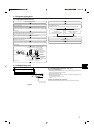
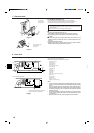
4. Indoor unit installation
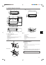
4.1. Suspension Structure (Give site of suspension
strong structure.)
4.1.1. Wooden structure (Fig. 4-1)
• Select tie beam (one-story houses) or second-floor girder (two-story houses) as
reinforcement member.
• Use sturdy beams of at least 6 cm square for beam pitch of 90 cm or less or of at
least 9cm square for beam pitch of 90-180 cm.
A Ceiling
B Rafter
C Beam
D Roof beam
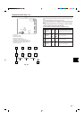
4.1.2. Ferro-concrete structures (Fig. 4-2)
Secure the suspension bolts using the method shown, or use steel or wooden hang-
ers, etc. to install the suspension bolts.
E Use inserts rated at 100-150 kg each (procure locally)
F Suspension bolts M10 (3/8") (procure locally)
G Steel reinforcing rod
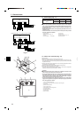
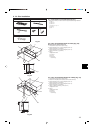
4.1.3. Installing the suspension bolts
• Check the pitch of the suspension bolts.
• Use the ø10 (3/8") suspension bolts (×4, procure locally).
• Adhere strictly to the length of the suspension bolts.
4.2. Suspending the unit (Fig. 4-3)
Direct suspension method:
Raise the unit and line it up with the suspension bolts, then secure it using both
nuts.
a Air outlet
b Air intake (selecting the either back side or bottom side.)
c Washer (procure locally)
d Nuts (procure locally)
e Suspension bolts (procure locally)
G
E
F
ab
b
ce
d
B
A
A
A
B
C
D
350
1070
Fig. 4-1
Fig. 4-3
Fig. 4-4
Fig. 4-2
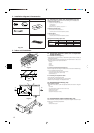
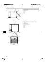
4.3. Transportation support removal (Fig. 4-4)
After installation, completely remove the transportation support because this part
should only be used during transportation.
A 3 screws
B Transportation support
C
4