


3
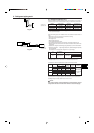
3. Installation diagram & Accessories
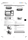
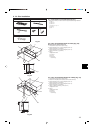
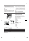
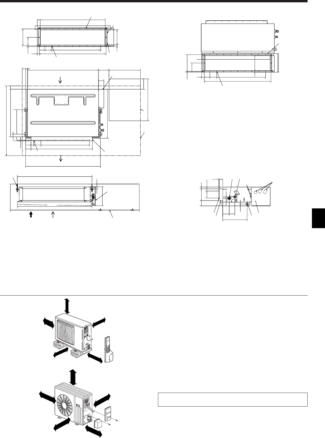
3.1. Indoor unit (Fig. 3-1)
1 Air inlet (rear side) *Select the either back side or bottom side
2 Electrical parts box
3 Suspension bolt pitch
5 Access door
6 Service space (It is necessary to maintain a working service area from the ceiling.)
7 Air inlet (bottom side) *Select the either back side or bottom side
8 Suspension bolt M10 or 3/8 (procure locally)
9 Air outlet duct flange
0 Air outlet
A Refrigerant pipe (gas)
(mm)
Fig. 3-1
■ SUZ-A09/A12AR
A
C
A
C
B
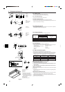
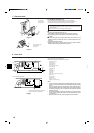
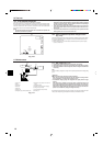
3.2. Outdoor unit (Fig. 3-2)
Ventilation and service space
■ SUZ-A09/A12AR
A 100 mm or more
B 350 mm or more
C Basically open 100 mm or more without only obstruction in front and on both sides of the
unit.
D 200 mm or more (Open two sides of left, right, or rear side.)
■ SUZ-A18/A24AR
A 100 mm or more
B 350 mm or more
C 500 mm or more
When the piping is to be attached to a wall containing metals (tin plated) or metal
netting, use a chemically treated wooden piece 20 mm or thicker between the wall
and the piping or wrap 7 to 8 turns of insulation vinyl tape around the piping.
Units should be installed by licensed contractor accordingly to local code require-
ment.
■ SUZ-A18/A24AR
A
D
C
A
B
42 930
7×100=700100
29
12.5 120
240
77.5
955
21525
H
J
I
G
J
50
27
1016
7×100=700
880
10040
(10)
50
60
350
38
680
50
1000
50
1070
150
77
450
150
600
700
2
1
3
0
3
5
6
9
8
3
2
5
7
A
(1070)
270
30
1100
2575
32.5
(10) 50
94 60
350
100
108
25
20
170
A
F
B
C
D
2
E
24012.5
120
25 215
39
77.5
100 7×100=700
955
93051
J
J
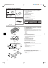
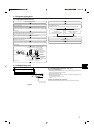
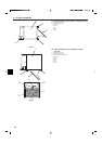
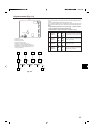
■ SEZ-A12/A18/A24AR
B Refrigerant pipe (liquid)
C Wiring entry
D Terminal block
E Drain plug R1 male
F Air outlet duct flange
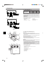
G In case of bottom side suction, mount the PLATE (A) on the rear side.
H After installation, remove the transportation support PLATE (B).
I PLATE (B) × 2
J Inlet size
A
Air inlet (bottom side) dimensions
PLATE (A)
24-ø2.9 holes
2×2-ø2.9 holes
20 or more
24-ø2.9 holes
Air inlet (rear side) dimensions
9×2-ø2.9 holes
Fig. 3-2