


13
10.1. Before test run
s After completing installation and the wiring and piping of the indoor and outdoor
units, check for refrigerant leakage, looseness in the power supply or control
wiring, wrong polarity, and no disconnection of one phase in the supply.
s Use a 500-volt megohmmeter to check that the resistance between the power
supply terminals and ground is at least 1.0 MΩ.
s Do not carry out this test on the control wiring (low voltage circuit) termi-
nals.
Warning:
Do not use the air conditioner if the insulation resistance is less than 1.0 MΩ.
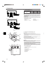
Insulation resistance
After installation or after the power source to the unit has been cut for an extended
period, the insulation resistance will drop below 1 MΩ due to refrigerant accumulat-
ing in the compressor. This is not a malfunction. Perform the following procedures.
1. Remove the wires from the compressor and measure the insulation resistance of
the compressor.
2. If the insulation resistance is below 1 MΩ, the compressor is faulty or the resist-
ance dropped due the accumulation of refrigerant in the compressor.
3. After connecting the wires to the compressor, the compressor will start to warm
up after power is supplied. After supplying power for the times indicated below,
measure the insulation resistance again.
• The insulation resistance drops due to accumulation of refrigerant in the com-
pressor. The resistance will rise above 1 MΩ after the compressor is warmed
up for two to three hours.
(The time necessary to warm up the compressor varies according to atmos-
pheric conditions and refrigerant accumulation.)
• To operate the compressor with refrigerant accumulated in the compressor,
the compressor must be warmed up at least 12 hours to prevent breakdown.
4. If the insulation resistance rises above 1 MΩ, the compressor is not faulty.
Caution:
• The compressor will not operate unless the power supply phase connection
is correct.
• Turn on the power at least 12 hours before starting operation.
- Starting operation immediately after turning on the main power switch can result in
severe damage to internal parts. Keep the power switch turned on during the op-
erational season.
10.Test run
10.2. Test run
The following 3 methods are available.
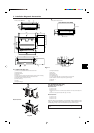
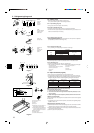
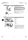
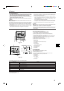
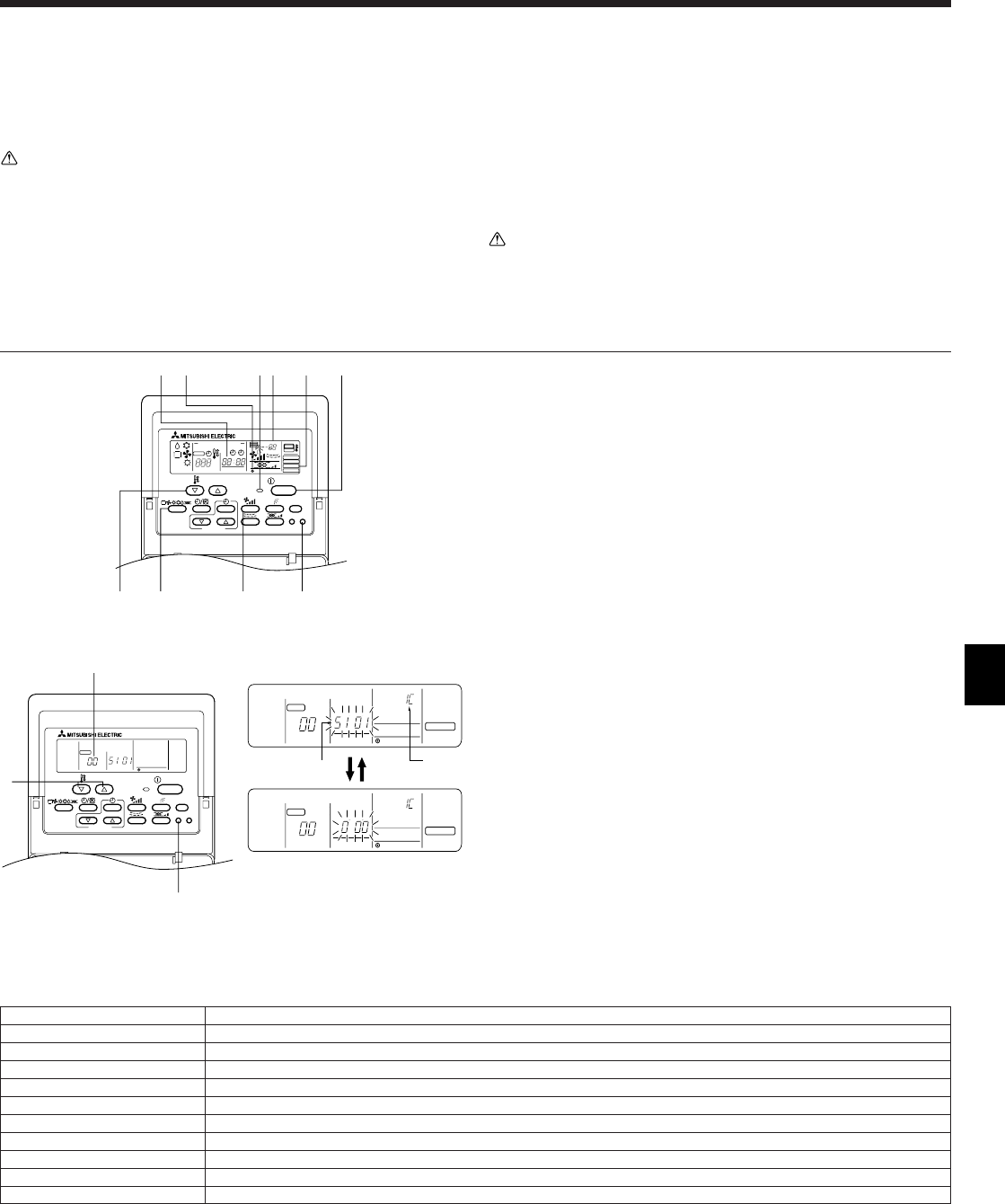
10.2.1. Using wired remote controller (Fig. 10-1)
1 Turn on the power at least 12 hours before the test run.
2 Press the [TEST] button twice. ➡ “TEST RUN” liquid crystal display
3 Press the [Mode selection] button. ➡ Make sure that wind is blown out.
4 Press the [Mode selection] button and switch to the cooling (or heating) mode.
➡ Make sure that cold (or warm) wind is blown out.
5 Press the [Fan speed] button. ➡ Make sure that the wind speed is switched.
6 Check operation of the outdoor unit fan.
7 Release test run by pressing the [ON/OFF] button. ➡ Stop
8 After the checks, always turn off the power.
A ON/OFF button
B Test run display
C Indoor temperature liquid line temperature display
D ON/OFF lamp
E Power display
F Error code display
Test run remaining time display
G Set temperature button
H Mode selection button
I Fan speed button
M TEST button
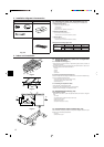
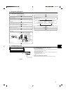
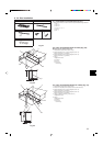
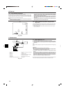
10.3. Self-check
10.3.1. Wired remote controller (Fig. 10-2)
1 Turn on the power.
2 Press the [CHECK] button twice.
3 Set refrigerant address with [TEMP] button if system control is used.
4 Press the [ON/OFF] button to stop the self-check.
A CHECK button
B Refrigerant address
C TEMP. button
D IC: Indoor unit
OC: Outdoor unit
E Check code
ON/OFF
CENTRALLY CONTROLLED
ERROR CODE
CLOCK
ON OFF
˚C
CHECK
CHECK MODE
FILTER
TEST RUN
FUNCTION
˚C
1Hr.
NOT AVAILABLE
STAND BY
DEFROST
FILTER
CHECKTEST
TEMP.
TIMER SET
DEF
HIMG
CBA
Fig. 10-1
ON/OFF
CHECK
FILTER
CHECKTEST
TEMP.
TIMER SET
B
C
A
STAND BY
DEFROST
INDOOR UNIT
ADDRESS NO
ERROR CODE
OA UNIT ADDRESS NO
CENTRALLY CONTROLLED
CLOCK
ON OFF
˚C
1Hr.
NOT AVAILABLE
˚C
CHECK MODE
FILTER
CHECK
FUNCTION
ERROR CODE
OA UNIT ADDRESS NO
STAND BY
DEFROST
INDOOR UNIT
ADDRESS NO
CENTRALLY CONTROLLED
CLOCK
ON OFF
˚C
1Hr.
NOT AVAILABLE
˚C
CHECK MODE
FILTER
CHECK
FUNCTION
a)
D
E
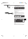
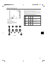
• For description of each check code, refer to the following table.
1 Check code Symptom
5101 Room temperature thermistor error
5102 RT12, 13 thermistor error
2503 Drain sensor error
2502 Drain pump error
1503 Freezing safeguard operation
0405, 1501, 4210, 5102 Outdoor unit error
6831~6834 Signal error between remote controller and indoor units
6800 Communication error between indoor and outdoor units
8000 No alarm history
F F F F No unit
• On wired remote controller
1 Check code displayed in the LCD.
Fig. 10-2