


Attach shielding ground on the outdoor unit’s ground terminal.
If the remote controller cable exceeds 10 m [32 ft], use a 1.25 mm
2
[AWG16] diameter cable over the exceeded portion, and add that
exceeded position to within 200 m [656 ft].
The BC controller is required only for simultaneous cooling and
heating series R2.
Connecting Line Voltage
Make sure power supply is off.
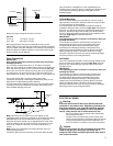
On the line voltage terminal block loosen the screws marked L1, L2
and G on the line voltage terminal strip. Insert line voltage wires and
tighten screws.
L1 G L2
7
Caution:
Wire the power supply so that no tension is imparted. Otherwise
disconnection, heating, or fire may result.
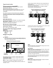
208 Volt Power Supply
The air handler comes from the factory with the 24VAC transformer
wired for a 230 volt supply voltage. For 208 volt power supply the line
voltage lead needs to be changed.
Remove the wire nut covering the orange wire. Disconnect the white
wire from the white lead going to the line voltage terminal strip.
Connect the orange lead to the white wire going to the line voltage
terminal strip using the wire nut. Now cover the white lead with the
remaining wire nut (see below)
For 208V power supply,
switch the transformer lead
marked 230V with the one
marker 208V. Reattach
wire nut to bare wire.
208/230VAC
24 Volts AC
24 VAC
T
L2 Black
230 V White
208 V Orange
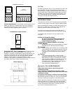
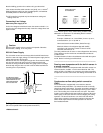
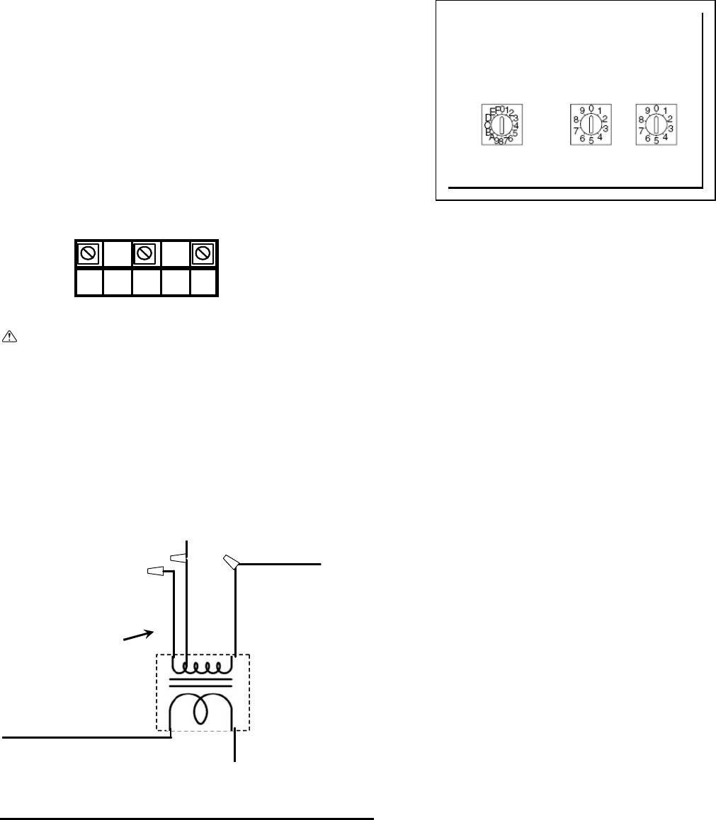
Setting addresses
(Be sure to operate with the main power turned OFF.)
<Address board>
Lower right corne
r
of circuit board
SW14 SW12 SW11
There are two types of rotary switch setting available: setting
addresses 1 to 9 and over 10, and setting branch numbers.
How to set addresses:
Example: If Address is “3”, leave SW12 (for over 10) at “0”,
and match SW11 (for 1 to 9) with “3”
How to set branch numbers SW14 (Series R2 only):
Match the indoor unit’s refrigerant pipe with the BC
controller’s end connection number. If there is no BC
controller used leave at “0”.
The rotary switches are all set to “0” when shipped from the factory.
These switches can be used to set unit addresses and branch
numbers at will.
The determination of indoor unit addresses varies with the system
at site. Set them referring to technical data.
_____________________________________
Sensing room temperature with the built-in sensor in
a remote controller
If you want to sense room temperature with the built-in sensor in a
remote controller, set SW1-1 on the control board to “ON”. The
setting of SW1-7 and SW1-8 as necessary also makes it possible
to adjust the air flow at a time when the heating thermometer is off.
_____________________________________
__
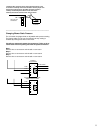
Condensate overflow safety switch connection
(CN31)
The circuit board is equipped with a connection to attach a
condensate safety float switch. The switch should be a normally
closed low voltage rated switch. The switch should be installed in a
location that it can sense a drain blockage causing a rise in water
level. This resulting rise in level will cause it to open. The switch
location is to be determined by the installing contractor. When the
switch opens, it will cause the LEV to close, stopping the cooling
operation. The fan will continue to run and a fault code will be
shown at the controller. Correcting the problem and closing the
switch will be required before normal operation can resume.
See installation below: