


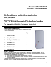
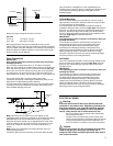
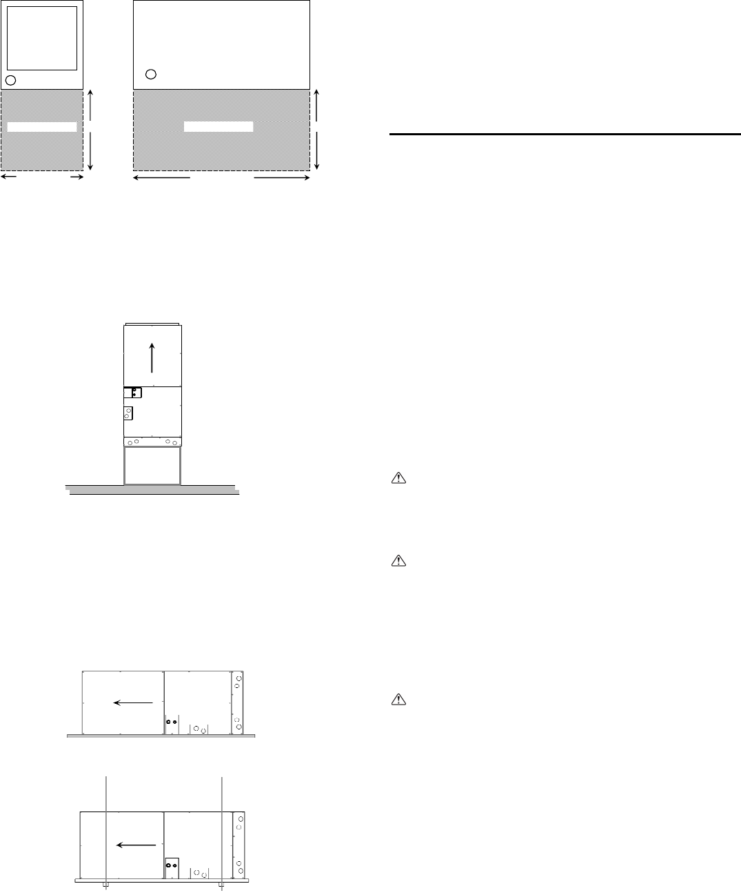
Installation Clearances
TOP View
Horizontal Installation
24"24"
Width of Unit
TOP View
Vertical Installation
Length of Unit
Clearance AreaClearance Area
4
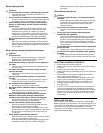
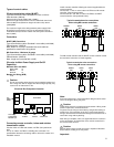
Vertical Applications: The air handler must be supported on the
bottom only and set on a solid floor with a return plenum below or
field supplied supporting frame or plenum. Securely attach the air
handler to the floor or supporting frame or plenum.
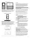
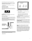
Horizontal (LEFT ONLY) Installations: No changes need to
be made to the unit for horizontal installation. The unit can be
installed on a platform or suspended from rails as shown below. The
rails must run the length of the unit and be of sufficient strength to
support the weight of the unit and connected ductwork. Vibration
isolation is recommended for horizontal installations. Some
jurisdictions may require an auxiliary drain pan be mounted under the
unit. Always follow local or national code requirements.
_____________________________________
Air Filter
An air filter (provided by others) is to be installed on the return side
of the air handler. The face area and pressure drop is to be
determined by the installing contractor based on the overall static
pressure performance of the system including supply and return
ductwork sizing. The factory static pressure performance is .30”
esp. A field selectable .50 esp. is available. See instructions for
changing to .50 esp in the electrical section.
REFRIGERANT PIPING
This piping work must be done in accordance with the installation
manuals for both outdoor unit and BC controller (R2/WR2 series)
Series R2 is designed to operate in a system that the refrigerant
pipe from an outdoor unit is received by the BC controller and
branches at the BC controller to the indoor units.
For constraints on piping length and allowable difference of
elevation, refer to the design section of the engineering manual.
Unit Mounted on Return Plenum
The method of pipe connection on the air handler is braze
connection.
Cautions of refrigerant piping
Be sure to use non-oxidative procedures for
brazing to ensure that no foreign matter or
moisture enters the piping.
ALWAYS USE A NITROGEN PURGE IN THE PIPING
DURING BRAZING
Provide proper bracing for refrigerant piping so no load is
imparted upon the connections at the air handler.
Warning:
When installing and moving the unit, do not charge it with
refrigerant other than the refrigerant specified on the unit.
Mixing of a different refrigerant, air, etc. may cause the
refrigerant cycle to malfunction and result in severe
damage.
Caution:
Use refrigerant piping made of C1220 (Cu-DHP)
phosphorous deoxidized copper as specified in ASTM
B280 Standard for copper and copper alloy seamless
pipes and tubes. In addition, be sure that the inner and
outer surfaces of the pipes are clean and free of
hazardous sulphur, oxides, dust/dirt, shaving particles,
oils, moisture, or any other contaminant.
Never use existing refrigerant piping.
Platform Mounting
Caution: COIL UNDER PRESSURE
Always wear safety glasses when working around
pressurized devices.
The air handlers are shipped with a nitrogen holding
charge in the coil. Carefully follow these instructions when
releasing the charge.
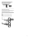
Suspended Mounting
The suction line stub contains a schrader valve where the factory
pre-charged the coil with nitrogen. This valve is located behind the
panel where the suction line comes out. This can be accessed by
removing the blower panel (top panel). (See drawing below)
Remove the cap and depress the schrader valve core to release
all pressure within the coil. Replace the cap and finger tighten.
Once all pressure is released the brazed ends of both tubes can
now be removed with a tubing cutter. If necessary ream the
connections to accept the refrigerant lines.