


Types of control cables
Wiring transmission cables (M-NET)
Types of transmission cable: Shielded wire CVVS or CPEVS
Cable diameter: (AWG16)
Maximum wiring length: Within 200 m (656ft.)
Maximum length of transmission lines for centralized control and
indoor/outdoor lines (Maximum length via indoor units): 500 m
[1640ft] MAX
The maximum length of the wiring between power supply (PAC-
SC51KUA) for transmission lines (on the transmission lines for
centralized control) and each outdoor unit and system controller is
200 m (656ft)
Controllers
M-NET (ME) Controllers
Type of transmission cable: Sheathed 2-core cable (unshielded)
Cable diameter: (AWG18)
Note: When 10 m (33 ft) is exceeded use same cable as
specified for transmission wiring above.
MA Controllers – Minimum 18 gauge
Type of transmission cable: Sheathed 2-core cable (unshielded)
Cable diameter: (AWG18)
Note: Length not to exceed 200 m (265’)
Wire size for Main Power Supply and On/Off
Capacities.
Minimum Wire size AWG
Main Cable: 14
Branch: 14
Ground: 14
Breaker for Wiring (NFB)
15 A
6
Caution:
Do not use anything other than the correct capacity breaker and
fuse. Using fuse, wire or copper wire with too large capacity may
cause a risk of malfunction or fire.
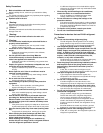
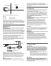
Fan
Speed
Relays
M1 M2 S
L1 G L2 1 2
Line Voltage
Terminal Strip Terminal Transformers
208/230V 1ph.
Electrical Box Component Location
12V DC 12V AC
TB15 TB5
Terminal
Low
Med
High
Circuit Board
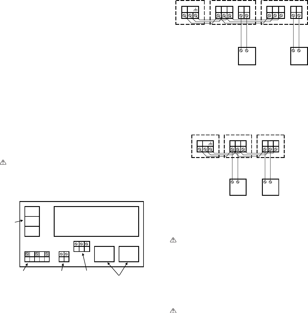
Connecting remote controller, indoor and outdoor
transmission cables
Connect indoor unit TB5 and outdoor unit TB3. (Non-polarized 2-
wire)
The “S” on indoor unit TB5 is a shielding wire connection. For
specifications about the connecting cables, refer to the outdoor unit
installation manual.
Install a remote controller following the manual supplied with the
remote controller.
Connect the “1” and “2” on the indoor unit TB15 to a MA remote
controller. (Non-polarized 2-wire)
Connect the “M1” and “M2” on indoor unit TB5 to an M-NET
remote controller. (Non-polarized 2-wire)
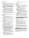
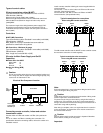
M1M2 M1M2 S 1 2 M1 M2 S 1 2
Outdoor
Unit
Indoor
Unit
Typical transmission wire connections
when using MA remote controllers
TB3 TB5 TB15
Indoor
Unit
TB5 TB15
MA
Controller
MA
Controller
The MA remote controller and the M-NET remote controller cannot
be used at the same time or interchangeably.
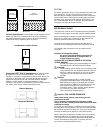
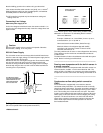
M1M2 M1M2 S M1M2 S
Controller
ME
Controller
Unit
TB3 TB5 TB5
Unit Unit
Typical transmission wire connections
when using ME remote controllers
ME
Outdoor Indoor Indoor
Note:
Ensure that the wiring is not pinched when fitting the terminal box
cover. Pinching the wiring may cut it.
Caution:
Install wiring so that it is not tight and under tension. Wiring under
tension may break or overheat and burn.
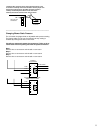
Fix power source wiring to control box by using buffer bushing or
tensile force. (PG connection or the like.) Connect transmission
wiring to transmission terminal block through the knockout hole of
control box using ordinary bushing.
After wiring is complete, make sure again that there is no tension
on the connections, and attach the cover onto the control box in
the reverse order removal.
Caution:
Wire the power supply so that no tension is imparted. Otherwise
disconnection, heating or fire may result.
Important: