


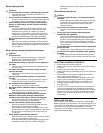
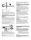
Schrader valve
Front panel
V
apor Connection
Cut here after
relieving pressure
5
Always use proper refrigerant line sizes as shown:
Unit size
P12, P18 1/4” liquid x 1/2” gas
P24 – P54 3/8” liquid x 5/8” gas
Both refrigerant lines need to be insulated all the way up to the
cabinet. Make sure the openings in the cabinet around the refrigerant
lines are sealed. 3/8 in thick insulation is the minimum recommended
thickness. Based on ambient conditions, local codes and line length,
thicker insulation may be desired.
Drain Connections
IMPORTANT!
Over-tightening the drain connections could result in drain pan
breakage and failure.
The air handler contains three sets of ¾” FPT drain connections.
When the unit is used in the vertical position, there are a left-hand set
and a right-hand set. When the unit is mounted horizontal (left only)
there is one set. Each set contains a primary drain and a secondary
or auxiliary drain. The primary drain is the one that is lowest (even
with the bottom of the pan). The secondary drain is at the higher level.
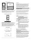
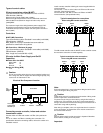
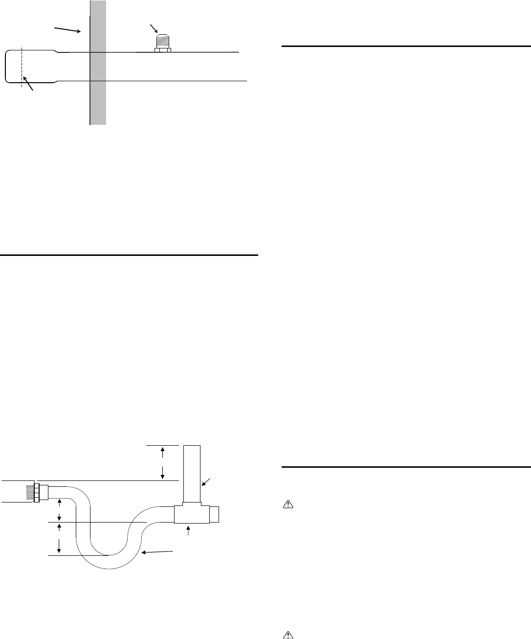
These units operate with a negative pressure at the drain
connections and require a drain trap be installed to prevent air from
being drawn in and preventing positive drainage.
The trap needs to be installed as close to the unit as possible. Make
sure the top of the trap is below the connection to the drain pan to
allow complete drainage of the pan.
2" Min.
Anti-syphon
air vent
2" Min.
2" Min.
Vent T
Drain Trap
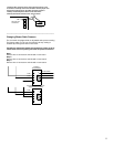
Note: Horizontal runs must also have an anti-siphon air vent
(standpipe) install ahead of the horizontal run to eliminate air trapping.
Horizontal drain lines must be pitched a minimum 1/8” per foot.
Route the drain lines outside or to an appropriate drain. Drain lines
must be installed so they do not block service access to the front of
the unit. 24” clearance in the front is for routine maintenance or
service.
Note: Check local codes before connecting the drain line to an
existing drainage system.
Insulate the drain lines where sweating could cause water damage.
Upon completion of installation, it is the responsibility of the
installer to ensure the drain pan(s) is capturing all condensate, and
all condensate is draining properly and not getting into the
ductwork/system.
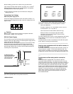
Vertical Mounting:
When mounted vertically, the air handler has a choice of left or
right hand drain connections. Select the drain connection set that
is most convenient for routing piping.
For left hand drains the connections are visible and ready for
installation. Attach the drain connectors finger tight and install the
drain line. For right hand remove the caps covering the drain pan
openings. Remove the plugs and reinstall in the left hand drain
opening. Install cover caps over these plugs. Now attach the drain
connector finger tight and install the drain line.
IMPORTANT!
Over-tightening the drain connection could result in drain pan
breakage and failure.
The secondary connection if used should be connected to a
separate drainage system. Run the secondary drain so the
occupants will be able to notice water flowing through the
secondary drain indicating a blockage in the primary drain.
Optional use for the secondary is a primary drain line overflow
switch (provided by others). This device will shut the cooling
operation unit down in the event of a primary drain line blockage.
See wiring section for connecting this device.
Horizontal:
If the unit is installed horizontally, remove the plugs installed in the
drain pan openings and attach connector finger tight and route
drain line. Any vertical drain pan openings must be covered to
eliminate air loss.
IMPORTANT!
Over-tightening the drain connection could result in drain pan
breakage and failure.
The secondary connection if used should be connected to a
separate drainage system. Run the secondary drain so the
occupants will be able to notice water flowing through the
secondary drain indicating a blockage in the primary drain.
Optional use for the secondary is a primary drain line overflow
switch (provided by others). This device will shut the cooling
operation unit down in the event of a primary drain line blockage.
See wiring section for connecting this device.
ELECTRICAL WIRING
Warning:
Electrical work should be done by a qualified electrical
contractor in accordance with “Engineering Standards for
Electrical Installation” and supplied installation manuals.
If the power circuit lacks capacity or has an installation
failure, it may cause a risk of electrical shock or fire.
− Be sure to follow local and national code requirements
when wiring these units
− Install the unit to prevent that any of the control circuit
cables (remote controller, transmission cables) is brought
in direct contact with the power cable outside the unit.
− Ensure that there is no tension on any wire connections
Caution:
Be sure to ground the unit. Do not connect the grounding
cable to any gas pipe, water pipe, lightening rod, or
telephone earth cable. Incomplete grounding may cause a
risk of electrical shock.