


8
DFEINLPGRRUTRCZSVSLHGPO
GB
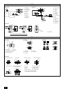
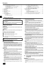
7. Installation of unit
7.1. Installation
[Fig. 7.1.1] (P.3)
A M10 anchor bolt procured at the site. B Corner is not seated.
C Fixing bracket for the hole-in anchor bolt (3 locations to fix with screws).
• Fix unit tightly with bolts so that unit will not fall down due to earthquakes or
strong winds.
• Use concrete or an angle bracket as the foundation of unit.
• Vibration may be transmitted to the installation section and noise and vibration
may be generated from the floor and walls, depending on the installation con-
ditions. Therefore, provide ample vibrationproofing (cushion pads, cushion
frame, etc.).
• Build the foundation in such way that the corner of the installation leg is se-
curely supported as shown in the figure. (Fig. 7.1.1)
When using a rubber isolating cushion, please ensure it is large enough to
cover the entire width of each of the unit's legs. If the corners are not firmly
seated, the installation feet may be bent.
• The projecting length of the anchor bolt should be less than 30 mm.
• Hole-in anchor bolts are not compatible with this product. However, if fixing
brackets are mounted on the 4 locations of the unit attachment part, hole-in
anchor bolts can be used.
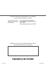
RP250
1 Connecting pipe (flange)
<Gas side>
1 pc.
2 Packing
(Inside
ø
23, Outside
ø
30)
1 pc.
4. Parts included list
Model
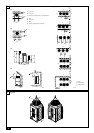
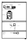
5. Space required around unit
1 In case of single installation
• Secure enough space around the unit as shown in the figure on page 2.
[Fig. 5.0.1] (P.2)
<A> Top view <B> Side view
<C> When there is little space up to an obstruction
A Front B Unit height
C Back D Air outlet guide (Procured at the site)
(1) If the distance is 300 mm or more between the rear side and the wall
(2) If the distance is 100 mm or more between the rear side and the wall
(3) If the wall height (H) of the front, rear or side exceeds the wall height
restriction
• When the height of the walls on the front, back or on the sides <H> exceeds
the wall height limit as defined here, add the height that exceeds the height
limit <h> to the figures that are marked with an asterisk.
<Wall height limit> Front: Up to the unit height
Back: Up to 500 mm from the unit bottom
Side: Up to the unit height
(4) If there are obstacles at the upper part of the unit
2 In case of collective installation
[Fig. 5.0.2] (P.2)
A Front B Must be open
C Wall height (H)
• When multiple units are installed adjacent to each other, secure enough space
to allow for air circulation and walkway between groups of units as shown in
the figures on page 2.
• At least two sides must be left open.
• As with the single installation, add the height that exceeds the height limit <h>
to the figures that are marked with an asterisk.
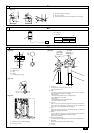
6. Lifting method
[Fig. 6.0.1] (P.2)
• Use suspension ropes that will withstand the weight of the unit.
• When moving the unit, use a 4-point suspension, and avoid giving impacts to
the unit (Do not use 2-point suspension).
• Place protective pads on the unit where it comes in contact with the ropes to
protect the unit from being scratched.
• Set the angle of roping at 40° or less.
• Use 2 ropes that are each longer than 8 meters.
• Place protective padding at the corners of the product to protect the product
from scratches or dents that might be caused by the rope.
Caution:
Be very careful when carrying/moving the product.
- When installing the outdoor unit, suspend the unit at the specified location of the
unit base. Stabilize as necessary so that it does not move to the side and support
it at 4 points. If the unit is installed or suspended with 3-point support, the unit
may become unstable and fall.
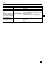
3. Specifications
Model
Noise level
External static pressure
Standard type
PUHZ-RP250YHM-A
58dB <A>
0 Pa
Operation temperature
Cooling mode: – 5°CDB ~ 43°CDB
Heating mode: – 12°CWB ~ 15°CWB
Warning:
• Be sure to install unit in a place strong enough to withstand its weight.
Any lack of strength may cause unit to fall down, resulting in a personal
injury.
•Have installation work in order to protect against strong winds and
earthquakes.
Any installation deficiency may cause unit to fall down, resulting in a
personal injury.
When building the foundation, give full attention to the floor strength, drain water
disposal <during operation, drain water flows out of the unit>, and piping and wir-
ing routes.
Precautions when routing the pipes and wires below the unit
When routing the pipes and wires below the unit, be sure that the foundation and
base work do not block the base through-holes. Also make sure the foundation is
at least 100 mm high so that the piping can pass under the unit.