


11
DFEINLPGRRUTRCZSVSLHGPO
GB
Caution:
Only use refrigerant R410A.
- The use of other refrigerants such as R22 or R407C, which contains chlorine,
will deteriorate the refrigerating machine oil or cause the compressor to malfunc-
tion.
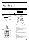
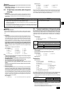
2 Evacuation
Evacuate with the valve of the outdoor unit closed and evacuate both the con-
nection piping and the indoor unit from the service port provided on the valve
of the outdoor unit using a vacuum pump. (Always evacuate from the service
port of both liquid pipe and gas pipe.) After the vacuum reaches 650 Pa [abs],
continue evacuation for at least one hour or more. Then, stop the vacuum
pump and leave it for 1 hour. Ensure the degree of vacuum has not increased.
(If the degree of vacuum increase is larger than 130 Pa, water might have
entered. Apply pressure to dry nitrogen gas up to 0.05 MPa and vacuum
again.) Finally, seal in with the liquid refrigerant through the liquid pipe, and
adjust the gas piping to obtain an appropriate amount of the refrigerant during
operation.
* Never perform air purging using refrigerant.
[Fig. 9.3.2] (P.4)
A System analyzer B Low knob C Hi knob
D Valve E Liquid pipe F Gas pipe
G Service port H Three-way joint I Valve
J Valve K R410A cylinder L Scale
M Vacuum pump N To indoor unit O Outdoor unit
Note:
•Always add an appropriate amount of refrigerant. Also always charge the
system with liquid refrigerant.
• Use a gauge manifold, charging hose, and other parts for the refrigerant
indicated on the unit.
• Use a graviometer. (One that can measure down to 0.1 kg.)
• Use a vacuum pump with a reverse flow check valve.
(Recommended vacuum gauge: ROBINAIR 14830A Thermistor Vacuum
Gauge)
Also use a vacuum gauge that reaches 65 Pa [abs] or below after operat-
ing for five minutes.
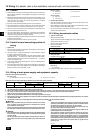
3 Refrigerant Charging
Since the refrigerant used with the unit is nonazerotropic, it must be charged in
the liquid state. Consequently, when charging the unit with refrigerant from a
cylinder, if the cylinder does not have a syphon pipe, charge the liquid refriger-
ant by turning the cylinder upside-down as shown in Fig. 9.3.3. If the cylinder
has a syphon pipe like that shown in the picture on the right, the liquid refriger-
ant can be charged with the cylinder standing upright. Therefore, give careful
attention to the cylinder specifications. If the unit should be charged with gas
refrigerant, replace all the refrigerant with new refrigerant. Do not use the re-
frigerant remaining in the cylinder.
[Fig. 9.3.3] (P.4)
A Syphon pipe B
In case of the R410A cylinder having no syphon pipe.
Heat
insulation
material A
Outer
covering B
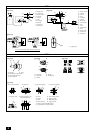
9.4. Thermal insulation of refrigerant piping
Be sure to add insulation work to refrigerant piping by covering liquid pipe and gas
pipe separately with enough thickness heat-resistant polyethylene, so that no gap
is observed in the joint between indoor unit and insulating material, and insulating
materials themselves. When insulation work is insufficient, there is a possibility of
condensation drip, etc. Pay special attention to insulation work in the ceiling ple-
num.
[Fig. 9.4.1] (P.4)
A Steel wire B Piping
C Asphaltic oily mastic or asphalt D Heat insulation material A
E Outer covering B
Glass fiber + Steel wire
Adhesive + Heat - resistant polyethylene foam + Adhesive tape
Indoor Vinyl tape
Floor exposed Water-proof hemp cloth + Bronze asphalt
Outdoor Water-proof hemp cloth + Zinc plate + Oily paint
Note:
• When using polyethylene cover as covering material, asphalt roofing shall
not be required.
• No heat insulation must be provided for electric wires.
[Fig. 9.4.2] (P.4)
A Liquid pipe B Gas pipe C Electric wire
D Finishing tape E Insulator
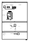
[Fig. 9.4.3] (P.4)
Penetrations
[Fig. 9.4.4] (P.4)
<A> Inner wall (concealed) <B> Outer wall
<C> Outer wall (exposed) <D> Floor (waterproofing)
<E> Roof pipe shaft
<F> Penetrating portion on fire limit and boundary wall
A Sleeve B Heat insulating material
C Lagging D Caulking material
E Band F Waterproofing layer
G Sleeve with edge H Lagging material
I Mortar or other incombustible caulking
J Incombustible heat insulation material
When filling a gap with mortar, cover the penetration part with steel plate so that
the insulation material will not be caved in. For this part, use incombustible mate-
rials for both insulation and covering. (Vinyl covering should not be used.)
• Insulation materials for the pipes to be added on site must meet the following
specifications:
* Installation of pipes in a high-temperature high-humidity environment, such as
the top floor of a building, may require the use of insulation materials thicker
than the ones specified in the chart above.
* When certain specifications presented by the client must be met, ensure that
they also meet the specifications on the chart above.
Caution:
Make sure to seal-off and excess space around areas where the wires and
refrigerant pipes enter the unit.
• Small animals, rainwater, or snow entering through the openings may
cause damage to the device.
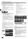
9.3. Airtight test, evacuation, and refrigerant
charging
1 Airtight test
Perform with the valve of the outdoor unit closed, and pressurize the connec-
tion piping and the indoor unit from the service port provided on the valve of
the outdoor unit. (Always pressurize from both the liquid pipe and the gas pipe
service ports.)
Restriction
• If a flammable gas or air (oxygen) is used as the pressurization
gas, it may catch fire or explode.
Airtight test procedure
(1) After pressurizing to the design pressure (4.15 MPa) using nitrogen gas, allow it to stand for
about one day. If the pressure does not drop, airtightness is good.
However, if the pressure drops, since the leaking point is unknown, the following bubble test
may also be performed.
(2) After the pressurization described above, spray the flare connection parts, brazed parts, and
other parts that may leak with a bubbling agent (Kyuboflex, etc.) and visually check for bubbles.
(3) After the airtight test, wipe off the bubbling agent.
[Fig. 9.3.1] (P.4)
A Nitrogen gas B To indoor unit C System analyzer
D Low knob E Hi knob F Valve
G Liquid pipe H Gas pipe I Outdoor unit
J Service port
Observe the following restrictions when conducting an air tightness test to prevent
negative effects on the refrigerating machine oil. Also, with nonazeotropic refriger-
ant (R410A), gas leakage causes the composition to change and affects perform-
ance. Therefore, perform the airtightness test cautiously.
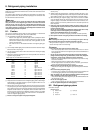
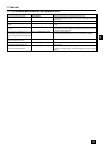
Thickness
Temperature Resistance
Pipe size
ø6.35 to 25.4 mm
10 mm min.
ø28.58 to 41.28 mm
15 mm min.
100°C min.