


12
DFEINLPGRRUTRCZSVSLHGPO
GB
1. Use dedicated power supplies for the outdoor unit and indoor unit.
2. Bear in mind ambient conditions (ambient temperature,direct sunlight, rain water,etc.) when proceeding with the wiring and connections.
3. The wire size is the minimum value for metal conduit wiring. If the voltage drops, use a wire that is one rank thicker in diameter.
Make sure the power-supply voltage does not drop more than 10%.
4. Specific wiring requirements should adhere to the wiring regulations of the region.
5. Power supply cords of parts of appliances for outdoor use shall not be lighter than polychloroprene sheathed flexible cord (design 245 IEC57). For example,
use wiring such as YZW.
6. A switch with at least 3 mm contact separation in each pole shall be provided by the Air Conditioner installer.
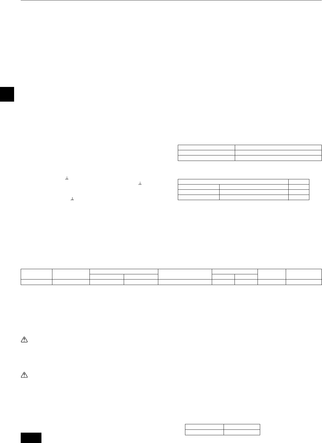
3032 324.0
Main cable
Local swtich (A)
Minimum wire thickness (mm
2
)
Capacity Fuse
Outdoor unit
Breaker for
wiring (NFB) (A)
Ground
RP250
Model
30A 100mA 0.1sec. or less
Breaker for current leakage
*1
Max. Permissive
System Impedance
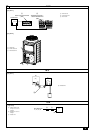
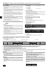
10.4. Wiring of main power supply and equipment capacity
Schematic Drawing of Wiring (Example)
[Fig. 10.4.1] (P.5)
A Switch (Breakers for wiring and current leakage) B Breakers for current leakage C Outdoor unit
Thickness of wire for main power supply, capacities of the switch and system impedance
10. Wiring (For details, refer to the installation manual of each unit and controller.)
10.1. Caution
1 Follow ordinance of your governmental organization for technical standard re-
lated to electrical equipment, wiring regulations and guidance of each electric
power company.
2 Wiring for control (hereinafter referred to as transmission line) shall be (5 cm or
more) apart from power source wiring so that it is not influenced by electric
noise from power source wiring (Do not insert transmission line and power
source wire in the same conduit).
3 Be sure to provide designated grounding work the to the outdoor unit.
4 Give some allowance to wiring for electrical part box of indoor and outdoor
units, because the box is sometimes removed at the time of service work.
5 Never connect the main power source to terminal block of transmission line. If
connected, electrical parts will burn out.
6 Use 2-core shield cable for transmission line. If transmission lines of different
systems are wired with the same multiplecore cable, the resultant poor trans-
mitting and receiving will cause erroneous operations.
7 Only the transmission line specified should be connected to the terminal block
for outdoor unit transmission.
Erroneous connection does not allow the system to operate.
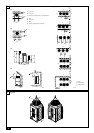
10.2. Control box and connecting position of
wiring
1 Outdoor unit
1. Remove the front panel of the control box by removing the 4 screws and push-
ing it up a little before pulling it out.
2. Connect the indoor - outdoor transmission line to the terminal block (TB3) for
the indoor - outdoor transmission line.
If multiple outdoor units are connected in the same refrigerant system, daisy-
chain TB3 (M1, M2,
Te r minal) on the outdoor units. Connect the indoor -
outdoor transmission line for the outdoor units to TB3 (M1, M2,
Terminal) of
only one of the outdoor units.
3. In the case of indoor-outdoor transmission line, connect the shield ground to
the grounding terminal (
).
4. Fix the connected wires securely in place with the cable strap at the bottom of
the terminal block. External force applied to the terminal block may damage it
resulting in a short circuit, ground fault, or a fire.
[Fig. 10.2.1] (P.5)
A Power source B Tr ansmission line
C Earth screw
[Fig. 10.2.2] (P.5)
A Cable strap B Power source line
C Tr ansmission line
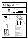
2 Conduit tube installation
• Close by hammering the knockout holes for the conduit tube located on the
base and the bottom part of the front panel.
• When installing the conduit tube directly through the knockout holes, remove
the burr and protect the tube with masking tape.
• Use the conduit tube to narrow down the opening if there is a possibility of
small animals entering the unit.
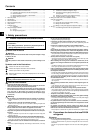
10.3. Wiring transmission cables
1 Types of control cables
1. Wiring transmission cables
•Types of transmission cables: Shielding wire CVVS, CPEVS or MVVS
• Cable diameter: More than 1.25 mm
2
• Maximum wiring length: Within 80 m
2. Remote control cables
• Remote Controller
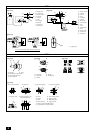
2 Wiring examples
• Controller name and symbol.
<Examples of transmission cable wiring>
[Fig. 10.3.1]
A Shielded wire
Set the address setting switch of all unit as zero (0). (factory setting)
Name Code
Outdoor unit
Indoor unit
Remote controller
Outdoor unit controller
Indoor unit controller
Remote controller
OC
IC
RC
Kind of remote control cable
Cable diameter
Remarks
Sheathed 2-core cable (unshielded) CVV
0.3 to 1.25 mm
2
(0.75 to 1.25 mm
2
)*
Within 200 m
* Connected with simple remote controller.
Warning:
• Be sure to use specified wires for connections and ensure no external
force is imparted to terminal connections. If connections are not fixed
firmly, heating or fire may result.
• Be sure to use the appropriate type of overcurrent protection switch. Note
that generated overcurrent may include some amount of direct current.
Caution:
• Some installation sites may require attachment of an earth leakage breaker
for the inverter. If no earth leakage breaker is installed, there is a danger
of electric shock.
• Do not use anything other than a breaker and fuse with the correct ca-
pacity. Using a fuse or wire of too large capacity may cause malfunction
or fire.
Note:
• This device is intended for the connection to a power supply system with
a maximum permissible system impedance shown in the above table at
the interface point (power service box) of the user’s supply.
• The user must ensure that this device is connected only to a power sup-
ply system which fulfils the requirement above.
If necessary, the user can ask the public power supply company for the
system impedance at the interface point.
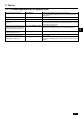
• This equipment complies with IEC 61000-3-12 provided that the short-
circuit power S
SC
is greater than or equal to S
SC
(*2) at the interface point
between the user’s supply and the public system. It is the responsibility
of the installer or user of the equipment to ensure, by consultation with
the distribution network operator if necessary, that the equipment is con-
nected only to a supply with a short-circuit power S
SC
greater than or
equal to S
SC
(*2).
S
SC
(*2)
RP250 1.27
Model S
SC
(MVA)
*1: Meets technical requirements of IEC61000-3-3
4.0